Quick definition: Filter pressure drop is the difference between inlet and outlet pressure measured at the same operating condition: ΔP = Pinlet − Poutlet. For a sintered mesh filter, a defensible estimate requires actual flow rate, fluid viscosity at operating temperature, effective filtration area, and either the permeability of the complete sintered laminate or a valid flow–pressure-drop point for the same clean element. Micron rating, mesh count, or outside diameter alone cannot determine pressure drop.
This guide is written for equipment designers, process engineers, and maintenance teams. It explains two traceable methods: a Darcy estimate based on measured permeability, and reference-point scaling based on test data from the same clean filter element. The examples demonstrate the calculation process only. They are not Alloyfilter product data and do not define an allowable differential pressure.
Contents
- Define the pressure-drop boundary
- Collect the required input data
- Method 1: Estimate media pressure drop with Darcy’s law
- Method 2: Scale a measured point for the same filter
- Choose the appropriate method
- Handle cylindrical, pleated, and parallel elements
- Understand why field results differ
- Build a usable flow–pressure-drop curve
- Frequently asked questions
Define the Pressure-Drop Boundary
A pressure-drop value is meaningful only when its measurement boundary is documented. If the upstream pressure tap is at the housing inlet and the downstream tap is at the housing outlet, the reading can include losses through inlet passages, supports, filter media, the internal core, connections, and outlet passages. A fixture that measures a flat sintered-mesh coupon produces a value closer to the resistance of the media itself.
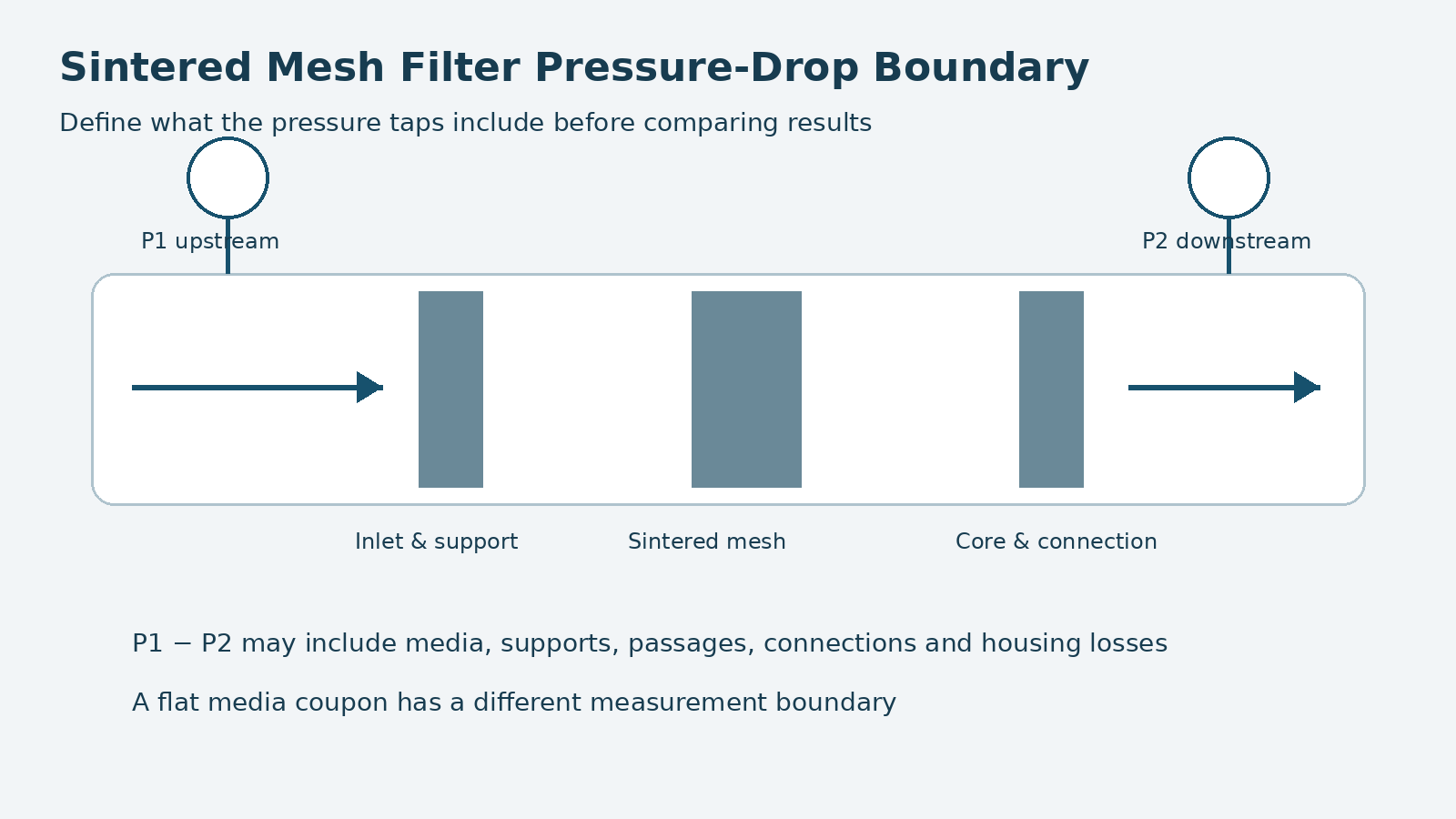
Decide whether the calculation should estimate the initial pressure drop of clean sintered mesh media, a completed filter element, or the complete filter housing. Darcy’s law is commonly used for viscous resistance through the porous medium. A finished element can add resistance from supports, seals, end fittings, and internal flow passages. Mixing test data from different boundaries makes the result unreliable.
Also separate three different pressure concepts:
- Operating pressure is the absolute or gauge pressure level in the system.
- Filter pressure drop is the difference between upstream and downstream pressure.
- Allowable differential pressure is the structural limit of a specific element under a defined direction, temperature, and support condition.
A calculated pressure drop of 0.1 bar does not prove the element’s operating-pressure rating or allowable differential pressure.
Collect the Required Input Data
| Input | Symbol and unit | How to obtain it |
|---|---|---|
| Actual volumetric flow | Q, m³/s | Use the actual flow at operating temperature and pressure. Gas flow needs additional treatment. |
| Dynamic viscosity | μ, Pa·s | Use data at operating temperature. 1 mPa·s = 1 cP. |
| Effective filtration area | A, m² | Exclude seals, welds, blocked edges, and other inactive regions. |
| Media thickness | L, m | Use the thickness of the complete sintered laminate associated with the permeability data. |
| Permeability | k, m² | Use measured permeability for the complete laminate in the actual flow direction. |
| Reference test point | Q₀, μ₀, ΔP₀ | Use a reliable point for the same clean element, boundary, and flow direction. |
If only kinematic viscosity ν is available, density ρ is also required, using μ = ρν. Convert all inputs to consistent SI units before applying the equations. Because liquid viscosity can change significantly with temperature, a room-temperature water test should not be used directly to represent hot oil without an appropriate correction.
Micron rating cannot replace permeability. Two laminates with the same nominal filtration rating may use different filter-layer weaves, support structures, total thicknesses, and sintering conditions. Their pressure drops may differ. Porosity, bubble-point, or air-permeability figures also cannot be substituted for k unless the test fluid, area, temperature, method, and units establish a valid conversion.
ISO 4022:2018 describes measurement of fluid permeability for permeable sintered metal materials with continuous interconnected porosity and expresses the result using viscous and inertia permeability coefficients. Its scope also identifies a limitation for long, small-bore hollow cylinders when pressure loss along the bore cannot be ignored.
Method 1: Estimate Media Pressure Drop with Darcy’s Law
For steady, single-phase Newtonian liquid flow within a verified linear Darcy range:
ΔP = μLQ / (kA)
Alternatively, using superficial velocity v = Q/A:
ΔP = μLv / k
Here, ΔP is the media pressure drop in pascals. With other conditions unchanged, increasing viscosity, thickness, or flow raises pressure drop. Increasing effective area or permeability lowers it. This relationship applies only to the specified medium, flow direction, and verified linear viscous range.
Worked Example
Assume a clean flat sintered-mesh laminate has permeability k = 2.0 × 10⁻¹² m², thickness L = 1.0 mm, and effective area A = 0.10 m². The liquid’s dynamic viscosity at operating temperature is μ = 1.0 mPa·s, and the actual flow is Q = 1.0 m³/h.
Convert to SI units:
- L = 0.001 m
- μ = 0.001 Pa·s
- Q = 2.778 × 10⁻⁴ m³/s
ΔP = (0.001 × 0.001 × 2.778 × 10−4) / (2.0 × 10−12 × 0.10)
The result is approximately 1,389 Pa, or 1.389 kPa / 0.0139 bar. It represents clean-media resistance for the assumed inputs. It does not include the housing, fittings, or local passage losses.
Our Sintered Mesh Filter Pressure Drop Calculator applies this equation and also provides reference-point scaling. Enter the permeability of the complete laminate. Do not use the open area of a protective mesh or a filter-layer mesh count as k, and do not reduce an already defined total effective area by open-area percentage a second time.
Method 2: Scale a Measured Point for the Same Filter
If reliable permeability is unavailable but a measured point exists for the same clean filter element, a nearby operating point may be estimated within a verified linear viscous range:
ΔP = ΔP₀ × (μ/μ₀) × (Q/Q₀)
The subscript 0 indicates the reference condition. This method retains the boundary of the reference measurement. If ΔP₀ was measured across the complete element, its structural losses are inherited by the estimate. Housing, valves, and pronounced inertial losses may not scale linearly with viscosity and flow.
Worked Example
A clean element has a measured pressure drop of 0.020 bar at 1 m³/h using a 1 cP liquid. The target liquid has a viscosity of 3 cP at operating temperature and the target flow is 2 m³/h. With the same geometry, direction, pressure-tap boundary, and flow regime:
ΔP = 0.020 × (3/1) × (2/1) = 0.120 bar
This is not a prediction of pressure drop after fouling. Deposited solids change the effective flow passages and resistance, so a clean-element relationship cannot represent the complete operating cycle.
Choose the Appropriate Method
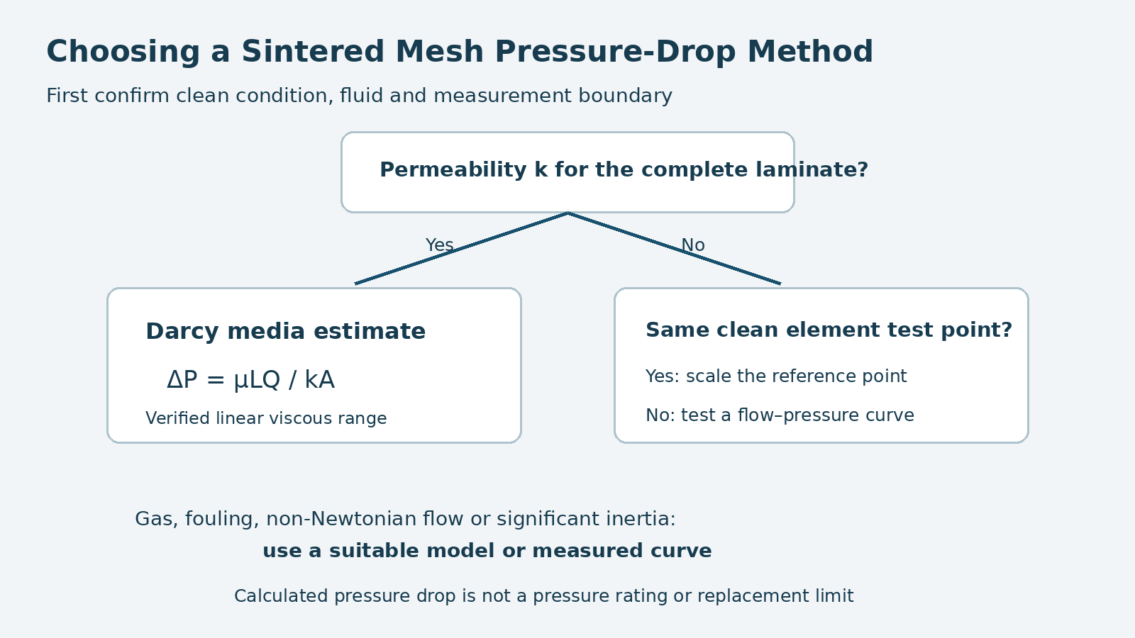
Use Darcy’s method when permeability of the complete laminate is known and the objective is clean-media resistance. Use reference-point scaling when a reliable test point exists for the same clean element and the target condition remains close to the verified linear range. When neither type of data is available, obtain a flow–pressure-drop curve instead of inferring pressure drop from micron rating.
If both viscous and inertia permeability coefficients are available, a model containing a velocity-squared term may be appropriate. This article does not invent an inertia term when the required coefficient is missing. The ISO 4022 framework is a reminder that a linear Darcy term alone is incomplete when inertia becomes significant.
Handle Cylindrical, Pleated, and Parallel Elements
Cylindrical Elements
For a thin-wall cylinder with approximately radial flow and wall thickness small relative to radius, the effective cylindrical surface area can be used as an engineering approximation. For thick-wall cylinders, the inner and outer areas differ enough that a cylindrical-coordinate model or measured data is more appropriate.
Pleated Elements
The developed geometric area of a pleated element is not automatically its fully effective area. Pleat-root contact, support blockage, end potting or welds, tight pleat spacing, and uneven flow distribution can reduce the active area. Subtract sealed and clearly obstructed regions before calculation.
Elements in Parallel
Total effective area can be used only when identical elements receive reasonably uniform flow and have comparable media and fouling condition. If branch resistances differ, flow will not divide equally; analyze the branches or measure the system curve.
Why Field Results May Differ
| Source of deviation | Effect | Check |
|---|---|---|
| Fluid temperature or formulation | Changes dynamic viscosity; some fluids become non-Newtonian | Use viscosity or rheology data at operating conditions |
| Gas compressibility | Density and actual volume change along the flow path | Use absolute pressure and a compressible-flow model |
| Inertial resistance | Pressure drop rises nonlinearly with velocity | Measure several flow points and fit valid coefficients |
| Filter cake or pore blockage | Permeability decreases during operation | Keep separate clean and operating curves |
| Supports, fittings, core, and housing | Add losses omitted by a media-only equation | Define the pressure-tap boundary or test components separately |
| Bypass or seal leakage | May reduce measured ΔP while compromising filtration | Inspect seals, welds, and assembly integrity |
| Overestimated area | Underestimates calculated pressure drop | Exclude blocked edges, seals, and inactive pleat regions |
A falling field pressure drop does not always mean the filter has recovered. It can also result from lower flow or bypass. A rising pressure drop is not always media blockage; valve position, fluid temperature, downstream backpressure, and pressure-instrument faults can change the reading. Trend comparisons should normalize or hold flow, temperature, fluid, and measurement points constant.
Build a Usable Flow–Pressure-Drop Curve
For engineering confirmation, test the clean sample or completed element at several increasing flow points. Record inlet and outlet pressure, actual flow, fluid, temperature, viscosity, flow direction, and measurement boundary. Allow each point to stabilize and check repeatability within the safe test range. Use linear scaling only if pressure drop is approximately proportional to flow over the range of interest.
The report should identify whether the test item is a media coupon, finished filter element, or element-and-housing assembly. Record effective area, dimensions, laminate structure or part number, instruments, and units. Compare the clean initial pressure drop with system capability and allowable differential pressure, while reserving margin for fouling and operating variation.
After cleaning or backwashing, repeat the measurement with the same fluid, temperature, and flow. Resistance recovery describes only the tested boundary. Continued use also depends on filtration integrity, deformation, welds, connections, and project-specific acceptance criteria.
Frequently Asked Questions
Can pressure drop be calculated directly from micron rating?
No. A micron rating has no unique permeability value. Use measured permeability for the complete laminate or flow–pressure-drop data for the same clean element.
Does adding more sintered mesh layers always increase pressure drop?
Layer count alone is insufficient. Weave, wire diameter, pore structure, compaction, thickness, and sintering condition all affect permeability. Compare complete laminates under the same test conditions.
Does the Darcy result represent the completed filter element?
Usually it represents porous-media resistance. Reference-point scaling can retain a complete-element boundary if the reference point was measured that way, but identical geometry and a valid flow range are still required.
Can this method calculate gas pressure drop?
The examples and dedicated calculator address steady, single-phase Newtonian liquids. Gas calculations need absolute pressure, temperature, compressibility, and possibly an inertia term. Use a suitable gas-flow model or measured curve.
Can clean pressure drop determine the replacement time?
No. Cleaning or replacement limits must be based on system capability, allowable differential pressure, filtration requirements, and validated maintenance criteria. Clean initial pressure drop is only a baseline.
Is maximum operating pressure the same as allowable differential pressure?
No. System pressure and pressure difference across the element are separate design quantities. Allowable differential pressure also depends on dimensions, support, flow direction, welds, connections, temperature, and material.
Summary
A useful sintered mesh filter pressure-drop calculation begins with the data boundary. Permeability-based Darcy calculations estimate clean-media viscous resistance. Same-element reference scaling estimates nearby conditions within a verified linear range. Both require actual flow, viscosity at operating temperature, correct effective area, and a consistent measurement boundary.
For compressible gas, significant inertia, non-Newtonian fluids, or a fouled element, use an appropriate model or measured curve. The calculation supports preliminary selection and technical review; it does not replace the pressure rating, allowable differential pressure, or acceptance testing of the finished element.
Author: Jack Sun. FILTALLOY TECHNOLOGY LTD is located in Anping, Hengshui, Hebei, China—widely known for wire-mesh manufacturing. Jack has long-term experience in woven metal mesh and industrial filter-element manufacturing.
Related resources:
Sintered Mesh Filter Pressure Drop Calculator
Sintered Mesh Filter Elements