Asymmetric Sintered Metal Filters for Gas and Liquid Filtration
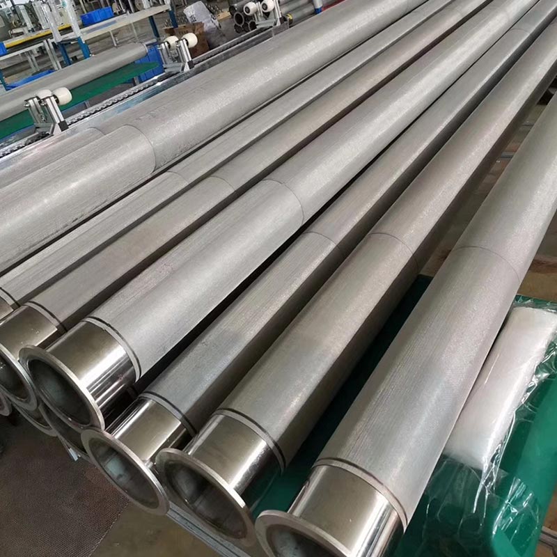
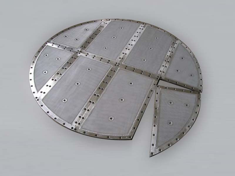
Filtalloy supplies asymmetric sintered metal filters made with fine and coarse metal powder regions. Tubular elements with end connections, sheets and other shapes are available to specification.
For our tubular elements, the fine filtration layer is on the inside and the coarser support is on the outside. Send your drawing or existing specification to discuss dimensions, connections and the required grade.

Asymmetric Sintered Metal Filter Specifications
| Code | Nominal filtration rating (μm) | Reference porosity (%) |
|---|---|---|
| ASM-F0.5 | 0.5 | 25 |
| ASM-F1.0 | 1 | 30 |
| ASM-F2.0 | 2 | 40 |
| ASM-F5.0 | 5 | 40 |
Confirmed size limits: maximum outside diameter 400 mm and maximum length 1600 mm. These maximum dimensions apply across the listed materials and do not vary by material. Finished dimensions, tolerances and connection details follow the approved drawing.
Custom inspection: the listed grades are nominal filtration ratings, with porosity shown as product reference data. Bubble-point testing can be specified with the wetting liquid, temperature, test procedure and acceptance criteria agreed for the ordered construction.
Identify fine-layer thickness and total wall thickness separately on the drawing. For a requirement outside the listed grades, send the target particle size and retention criterion so we can review the corresponding construction and test basis.
Materials and Element Design
Material options include 304L and 316L stainless steel, nickel, titanium, Monel, Inconel and Hastelloy. Specify the exact alloy grade rather than the alloy family alone. Material availability and suitability are reviewed for the selected filtration grade, process chemistry and operating temperature.
- 304L stainless steel
- 316L stainless steel
- Nickel
- Titanium — specify the required grade
- Monel — specify the required grade
- Inconel — specify the required grade
- Hastelloy — specify the required grade
For a replacement cartridge, provide the outer diameter, inner diameter, filtration length, overall length, end connections and sealing details. If the filtration region and support require different materials, include this requirement for technical review.
Finished Filter Configuration Checklist
Define the finished component together with the filtration medium. Use the drawing to identify the end fittings and installation interfaces.
| Item | Supply and order details |
|---|---|
| Supply forms | Tubular filters supplied as finished elements with end connections; sheets and other shapes are also available for long-term supply. |
| Filtration structure | Fine inner layer and coarse outer support for tubular elements; specify fine-layer and total wall thickness on the drawing. |
| Nominal rating | 0.5, 1, 2 or 5 μm reference grades; agree any retention-efficiency requirement and test method separately. |
| Dimensions | Maximum porous body OD 400 mm; maximum length 1600 mm across the listed materials. Specify ID, effective porous length, overall length and tolerances. |
| Connections and seals | Provide the end-fitting drawing, interface dimensions, sealing arrangement and seal material where applicable. |
| Operating duty | Process medium, contamination, flow, viscosity where relevant, temperature, pressure, filtration direction and allowable forward/reverse differential pressure. |
| Inspection | Agree dimensional checks, material documentation and the required integrity, flow or filtration checks, including their conditions and acceptance limits. |
How the Asymmetric Metal Powder Structure Works
Here, “asymmetric” describes the difference in powder particle size across the filter wall, rather than an uneven outer shape. In our tubular elements, the fine-powder filtration layer is on the inside and the coarser porous support is on the outside.
Comparing asymmetric and uniform powder structures
| Comparison field | Keep aligned or identify the difference |
|---|---|
| Geometry and layers | Same active area, total wall thickness, material, fine-layer thickness and support arrangement; retain any differences explicitly. |
| Performance basis | Same grade definition, test fluid, temperature, flow/area basis and pressure boundary. Align the rating definitions before using the results to compare candidates. |
| Finished assembly | Include connections, seals, support and normal/reverse flow conditions. Use the complete construction to assess cartridge operating limits. |
To evaluate the effect of fine-layer thickness, compare the proposed structures at the same retention target and matched flow conditions, recording the relevant geometry and material differences. For residual deposits or abnormal recovery, use the metal filter troubleshooting guide.
The fine region provides the filtration layer and the coarse region provides the porous support. Assess permeability and retention with the finished pore structure, thickness and material; assess pressure resistance with the complete element. Use the approved operating specification and assembly connections to establish filtration and backwashing directions.
Reading the flow arrows on a tubular filter drawing
Example for a design that feeds the bore during filtration. The arrows show flow through the wall.
Normal filtration: Bore → fine inner layer → coarse outer support → housing side.
Reverse flow, when specified: Housing side → coarse outer support → fine inner layer → bore.
Check the feed and filtrate connections on the approved assembly drawing. If reverse cleaning is specified, confirm the cleaning flow path, discharge route and permitted reverse differential pressure in the operating procedure.
Powder Size, Pore Size and Filtration Rating
Use powder particle size to describe the raw material, pore size to describe the sintered openings and connected passages, and filtration rating to state the retention requirement under its test method. Keeping these definitions with the specification makes the material and performance requirements clear.
The 0.5, 1, 2 and 5 μm grades in the following table are nominal filtration ratings. For a defined removal efficiency, add the target particle size, test method and acceptance criterion. Retain bubble point as its own pore-test result; particle retention is established by the corresponding filtration evidence.
Inspection and Acceptance Requirements
Agree the inspection plan before manufacture. It can address dimensions and connection fit, material documentation, porous-structure integrity, bubble point, permeability or flow, and pressure resistance where applicable. The agreed plan defines the method, test conditions, acceptance limits and sampling frequency.
If a particle-retention percentage is required, define the challenge particles, particle-size range, fluid, flow conditions and measurement method. Pressure resistance must relate to the complete element and its intended direction of loading.
Applications for Gas and Liquid Particle Filtration
Applications include catalyst filtration and recovery in refining and petrochemical processes, industrial gas and liquid fine-particle filtration, and particle filtration in battery-material processing. Suitability is reviewed against the actual process fluid and particle load.
For catalyst recovery, provide the catalyst particle-size distribution, solids concentration, solvent and operating cycle. For liquid clarification, include viscosity at the operating temperature and the required filtrate quality. For gas filtration, specify gas composition, temperature, flow reference conditions and particle loading.
For a sterile-filtration or dissolved-substance separation requirement, begin with the intended separation task and its acceptance criteria. Those duties need their own validation; the listed micron grade addresses the stated particle-filtration requirement.
Backwashing, Cleaning and Reuse
Where the fine filtration layer is operated on the feed side, retaining particles near that surface can support cake release and cleaning. Backwashing or reverse-gas cleaning must be compatible with the element’s layer arrangement, connections and permitted reverse differential pressure.
Choose cleaning liquids and procedures around the contamination and material compatibility. Solvent cleaning, ultrasonic cleaning or other methods should be agreed for the specific element. Check flow or permeability, pressure drop and integrity after cleaning under comparable test conditions before returning the element to service.
Asymmetric Sintered Metal Filter FAQs
What makes a sintered metal filter asymmetric?
Different metal powder particle sizes form a fine inner filtration layer and a coarser outer support region in the tubular filter wall. This difference across the wall produces the asymmetric porous structure.
Where is the fine filtration layer located?
In our tubular asymmetric sintered metal filters, the fine filtration layer is on the inner side and the coarser porous support is on the outer side. Filtration and backwashing directions must follow the approved operating specification.
Is powder particle size the same as filtration rating?
Powder size describes the starting material. Use the specified finished-element filtration test to define particle retention, and record both requirements separately where needed.
Can the filter be backwashed?
For a backwashing proposal, identify the deposit, flow path and permitted reverse differential pressure for the actual layer arrangement. Agree the procedure and limits, then check flow recovery and integrity after cleaning before reuse.
How does this differ from a sintered wire mesh filter?
This asymmetric element uses fine and coarse metal powders across the wall. A sintered wire mesh filter uses bonded layers of woven wire mesh. They are different media structures and should be selected against the filtration duty.
What information is needed for a replacement element?
Start with the drawing, specification or sample information and required quantity. Mark the dimensions, connections and sealing features that must match the installation. Add the material, filtration requirement and operating or cleaning details relevant to the replacement; we can clarify remaining manufacturing requirements with you.
Send Your Drawing, Specification or Sample Photos
Send the drawing or existing specification you have, together with the quantity and the parts you need. Sample photos and main dimensions are a useful starting point when a drawing is unavailable.
If you are still defining the product, briefly describe its intended use. We will clarify the additional manufacturing and inspection details with you.