Sintered metal fiber felt is a porous filter medium made by laying metal fibers and sintering their contact points. It can be supplied as flat media or fabricated into cylindrical and pleated filter elements, with a woven wire mesh support layer where the design requires one. Selection starts with the fluid, temperature, corrosion conditions, filtration requirement, dimensions and cleaning method.
The interconnected fiber network provides flow paths and space for retained particles. Final performance depends on the fiber structure, thickness, material, support and element geometry. No single porosity or rating number describes every material and design.
Main Features
• The connected pore network can combine permeability with space for retained particles.
• Actual pressure drop depends on flow, fluid, construction and contamination.
• Woven mesh support and pleated configurations are available where appropriate.
• Material and structure are selected for temperature, corrosion conditions and cleaning requirements.
• Cleanability must be assessed for the finished element and operating conditions.
Materials and Available Forms
Stainless steel 316L
Stainless steel 310S
Titanium
Nickel
Hastelloy
Inconel
FeCrAl
Each material must be checked against the actual fluid, temperature and corrosion conditions.
Item
Available information
Form
Flat media; mesh-supported media; cylindrical or pleated filter elements
Overall thickness range
0.10–1.50 mm
Titanium fiber felt porosity
50–80%
Nickel fiber felt porosity
50–85%
Standard Sheet Sizes
500 × 1000 mm
600 × 1000 mm
600 × 1200 mm
1000 × 1000 mm
1000 × 1200 mm
1000 × 1480 mm
1180 × 1450 mm
1180 × 1500 mm
Custom Size Range
Maximum sheet size: 1500 × 1800 mm
Thickness: 0.10–1.50 mm
Porosity varies with material and construction. The SFF-F rows below are not assigned to a specific material in this page.
Applications
Gas and liquid filtration: process filtration, steam and ammonia handling, hydraulic filtration and prefiltration.
Dust, powder and melt filtration: high-temperature dust removal, polymer and polyester melt filtration, catalyst recovery, gasification and pharmaceutical powder recovery.
Electrolyzer components: porous metal media may also be considered for PEM, AEM and alkaline electrolyzers.
Material and finished-element suitability must be checked against the actual fluid, temperature, filtration requirement and component design.
Structure and Specifications
Metal fiber felt may be supplied alone or combined with woven mesh for support. Fiber preparation, layup, pressing, sintering, post-sintering leveling and fabrication each affect the final dimensions and pore structure. The manufacturing images below illustrate the process stages; they do not establish a filtration rating or dimensional tolerance by themselves.
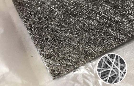
Metal fiber felt sheet surface
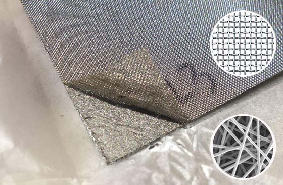
Metal fiber felt with mesh support
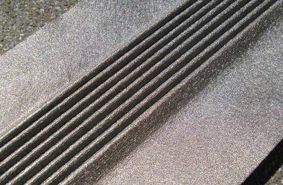
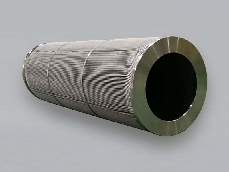
Pleated metal fiber felt media
Manufacturing Process
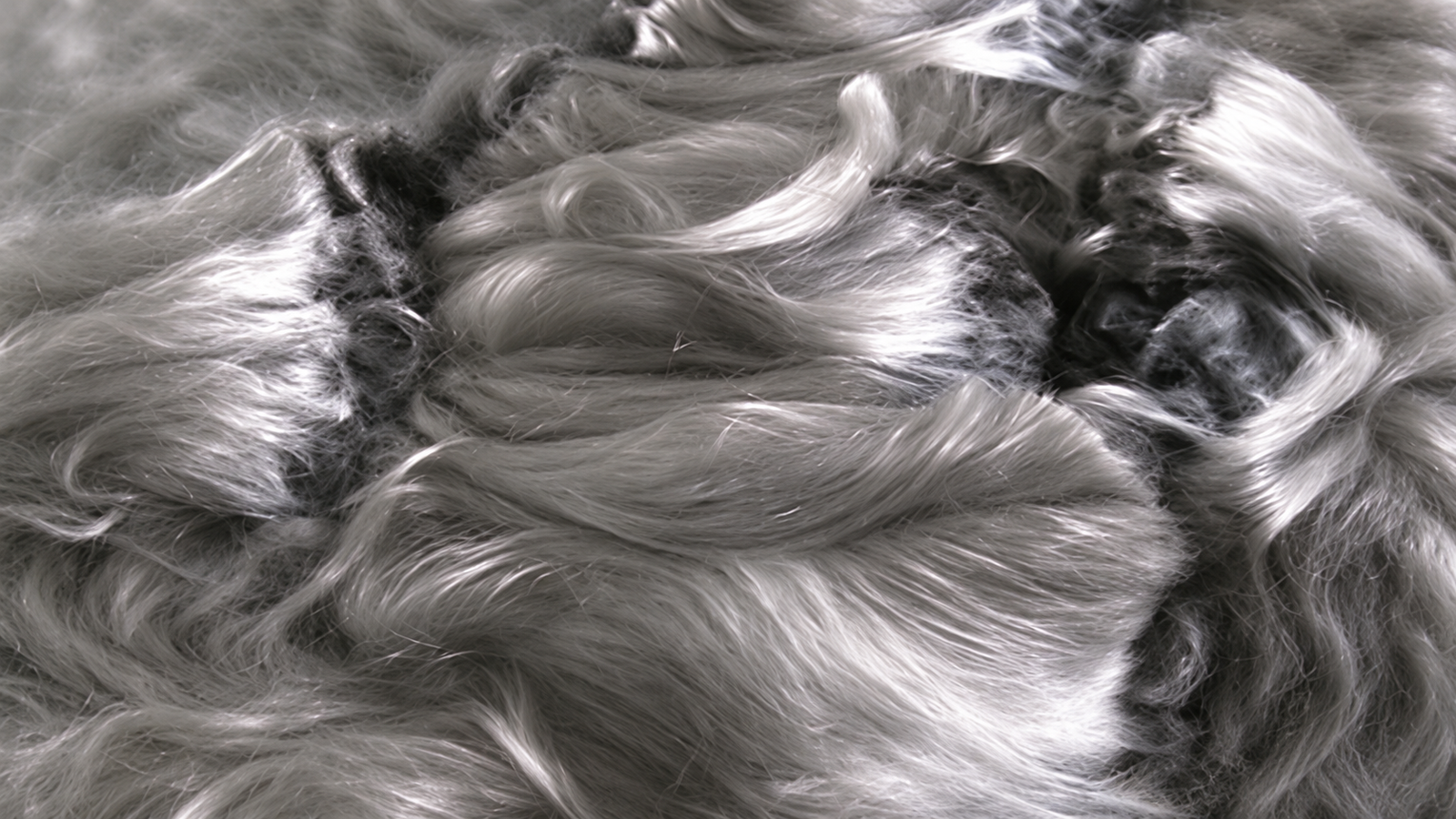
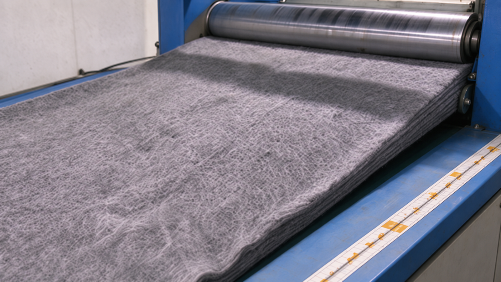
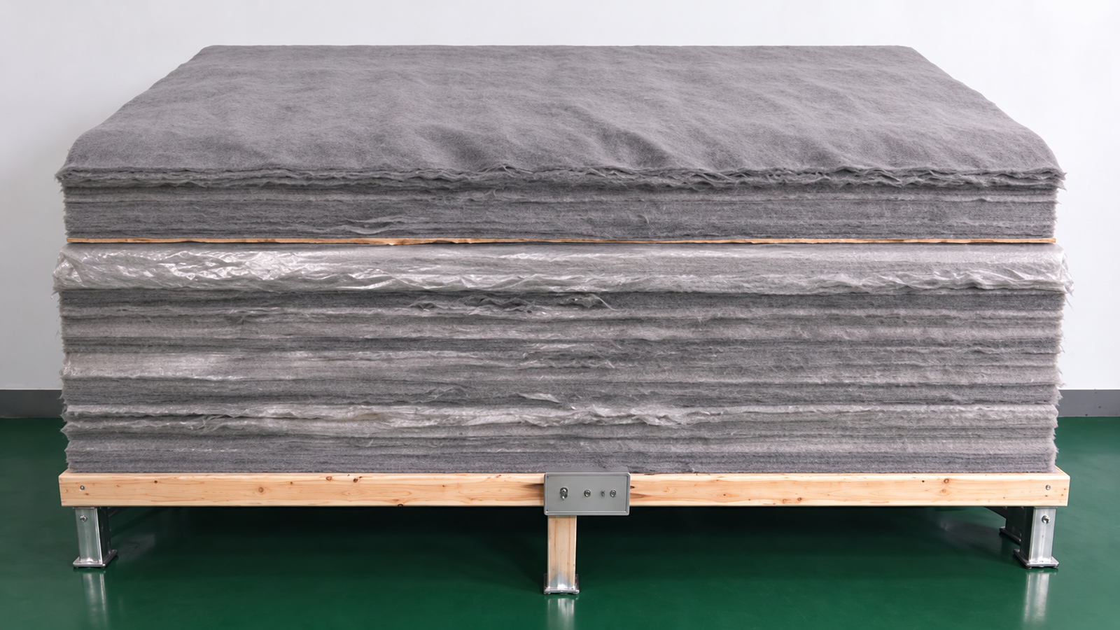
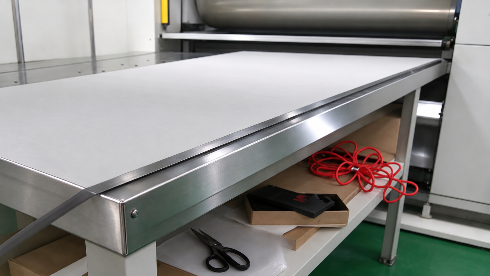
The four images illustrate metal fiber preparation, fiber layup, pressing after layup and post-sintering leveling. These process illustrations are not photographs of a particular production batch or product test records.
1. Metal fiber preparation (process illustration)
2. Metal fiber layup (process illustration)
3. Pressing after fiber layup (process illustration)
4. Post-sintering leveling (process illustration)
SFF-F Specification Data
Code
Rating
Thickness
Thickness
Porosity
Bubble Pt.
Bubble Pt.
Air Permeability
Tensile Strength
μm
mm, ±10%
in, ±10%
±5%
Pa, ±8%
psi, ±8%
L/dm²·min, ±10%
MPa, ±10%
SFF-F3
3
0.3
0.012
67
12000
1.740
13
48
SFF-F5
5
0.4
0.016
70
7000
1.015
30
45
SFF-F10
10
0.5
0.020
75
3500
0.508
100
44.5
SFF-F15
15
0.68
0.027
80
2300
0.334
180
30.5
SFF-F20
20
0.68
0.027
80
1700
0.247
300
30.5
SFF-F25
25
0.68
0.027
80
1400
0.203
350
30.5
SFF-F30
30
0.68
0.027
80
1100
0.160
600
30.5
SFF-F40
40
0.68
0.027
80
900
0.130
650
30.5
SFF-F60
60
0.68
0.027
85
800
0.116
1000
19.0
SFF-F80
80
0.68
0.027
85
700
0.102
1300
19.0
Bubble point: tested according to ISO 4003.
Air permeability: tested according to ISO 4022.
Existing Product Gallery
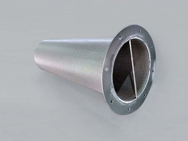
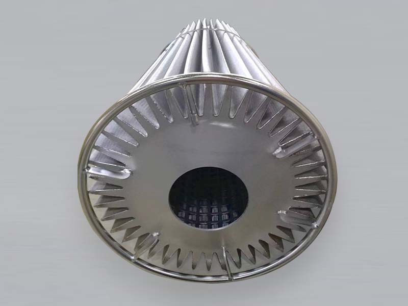
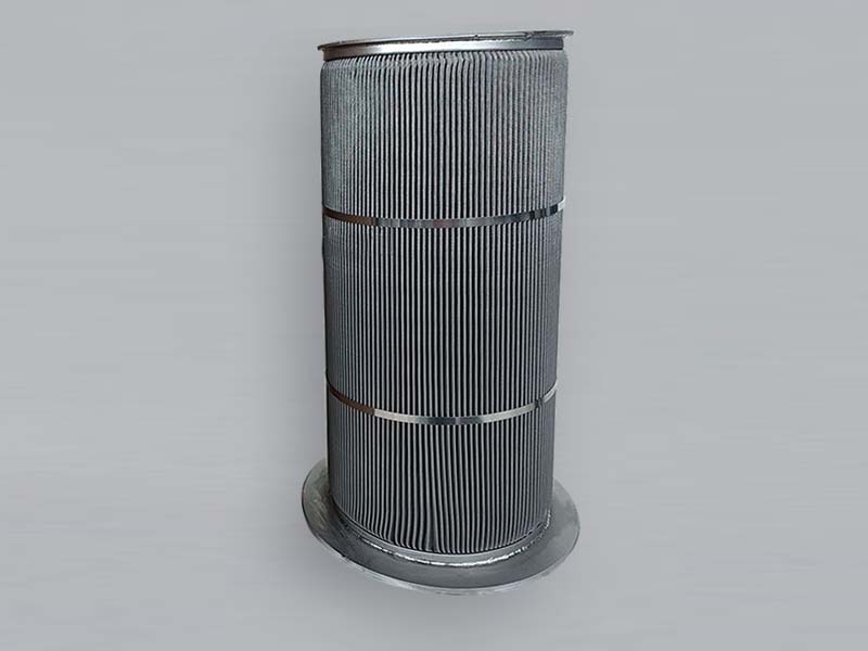
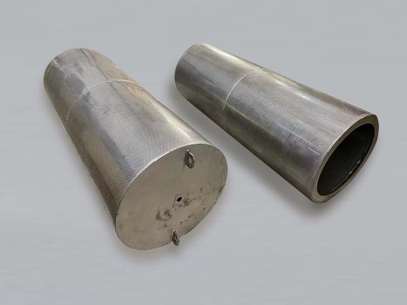
Gallery labels describe visible shapes and construction only. The SFF-1 to SFF-10 photo numbers do not identify material, filtration rating or operating application.
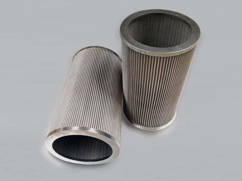
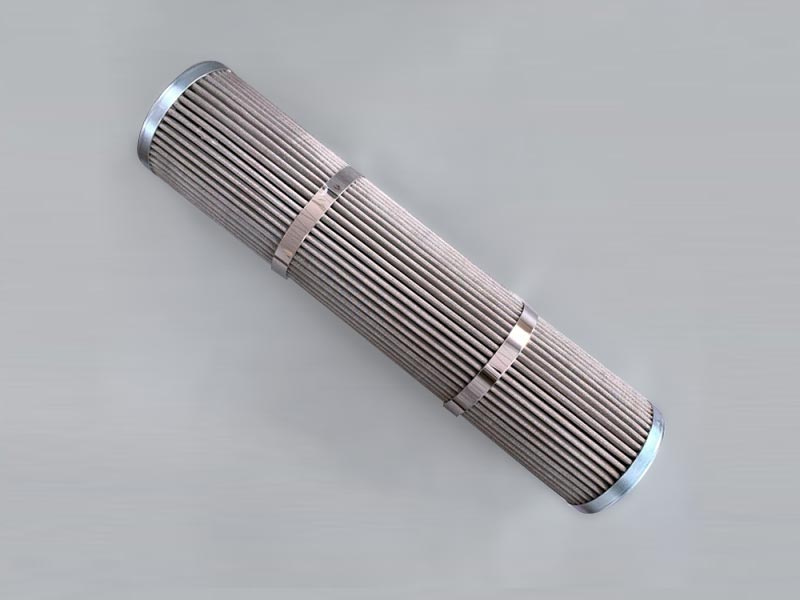
SFF-1 | Pleated cylindrical element with reinforcement rings
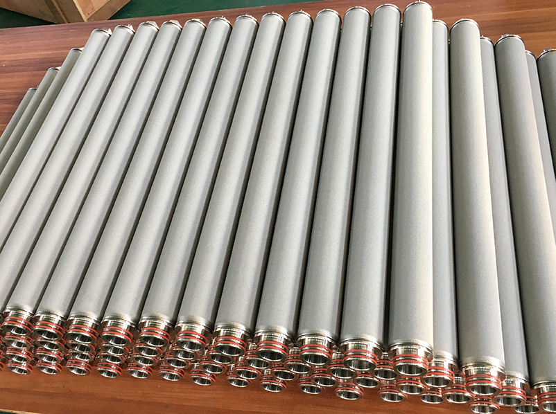
SFF-2 | Cylindrical element and end fitting
SFF-3 | Pleated cylindrical filter element
SFF-4 | Pleated element with outer support bands
SFF-5 | Pleated element and end connection
SFF-6 | Joined pleated filter sections
SFF-7 | Cylindrical pleated filter element
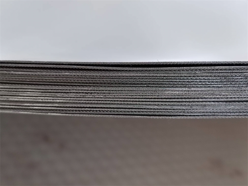
SFF-8 | Metal fiber felt sheet surface
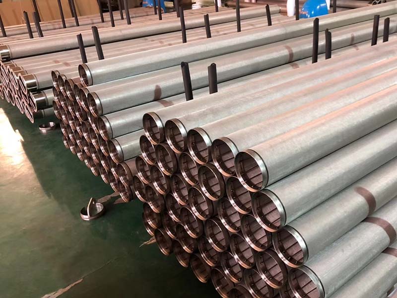
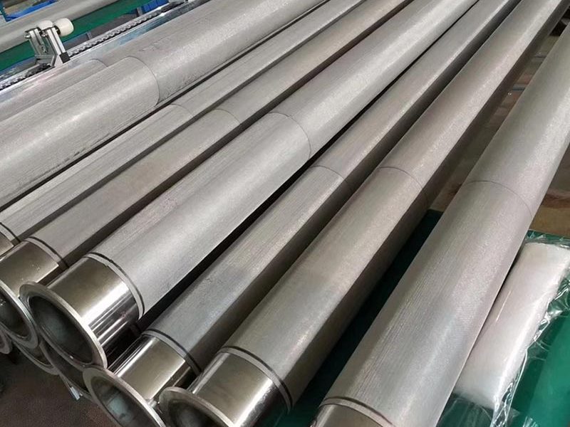
SFF-9 | Cylindrical filter elements
SFF-10 | Metal fiber felt sheets
Frequently Asked Questions
Does metal fiber felt always include support mesh?
No. It can be supplied as fiber felt alone or combined with woven wire mesh, depending on pressure direction, strength requirements and element design.
Does higher porosity always mean better filtration?
No. Compare the required rating with pore structure, thickness, flow, pressure drop and dirt holding capacity under the actual operating conditions.
Can the table alone define the material and finished element?
No. The table does not assign each SFF-F row to a material, and finished element dimensions, connections and support must be confirmed separately.
Discuss Your Filtration Requirements
Choose the path that matches your project:
Custom Design for a New Project
For a new filtration application, discuss the operating conditions and required finished product with us. Provide the fluid and particles, target filtration rating, flow, temperature, pressure, allowable pressure drop, installation space and cleaning method. We can work through material, media structure, element shape, support and connection details, then agree on drawings, samples and checks before production.
Build to Drawing for Replacement
To replace an existing product when you have drawings or specification data, send the drawings, dimensions and tolerances, material, filtration rating, connections and relevant operating conditions. We will review the requirements and manufacture the replacement to the agreed drawing and specification.
Recreate from an Existing Sample
If you have no drawing or complete data, send us an existing sample. We can measure its dimensions, inspect its construction and connections, and document the specifications that can be recovered. We will confirm any uncertain material or performance requirements with you before reproducing the product; a used sample alone may not establish its original filtration rating.