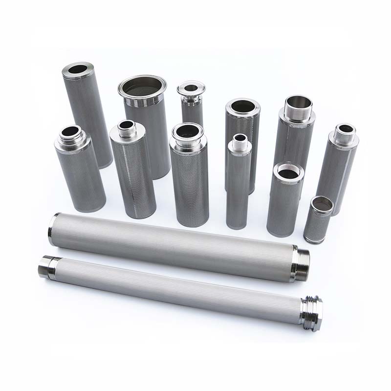
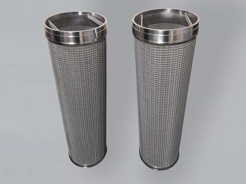
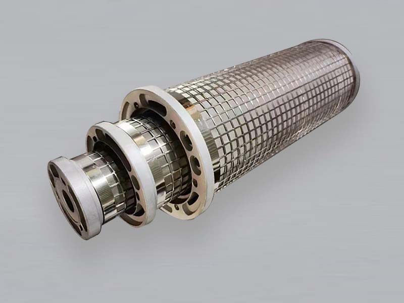
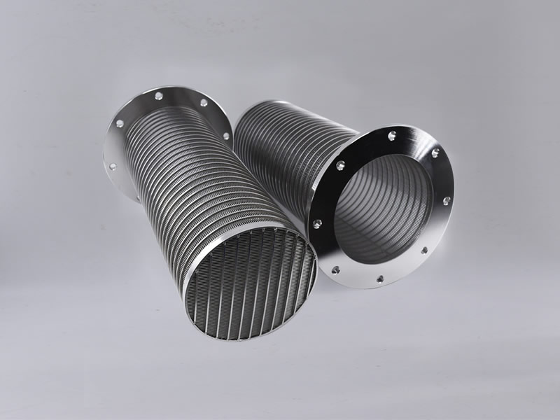
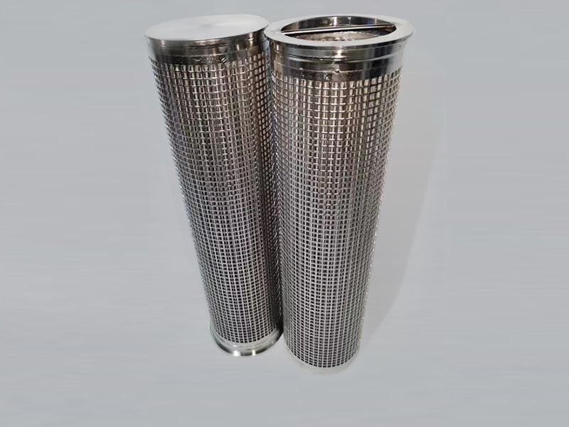
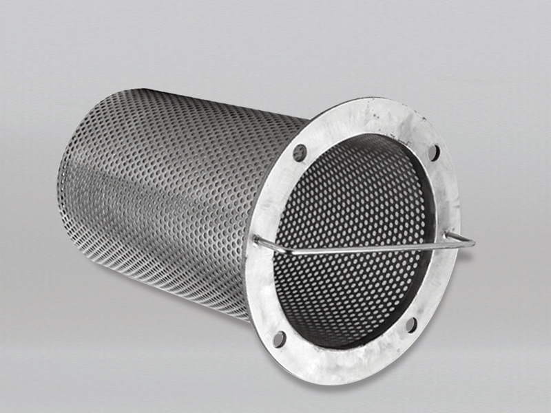
Sintered mesh filter elements use diffusion-bonded layers of metal wire mesh as the filtration medium. The filtration layer, protective layers and support layers can be configured for a disc, panel or cylindrical element according to the application. The number and arrangement of layers vary by design.
Share the medium, particle target, flow, allowable pressure drop, installation dimensions and cleaning method. We can then review the mesh structure, material, connection and checks for a manufacturable element. A filter medium’s nominal rating does not by itself establish the finished element’s retention efficiency or operating pressure drop.
Product advantages and operating limits
Diffusion-bonded layers provide a stable filtering surface and supporting structure suited to the specified element design.
Filter, protection and support layers can be configured to the filtration target and forming method.
A differential pressure capability of up to 3000 PSI may apply to a suitable specified design; verify material, layer structure, size, support, welds, connection and pressure direction for the exact element.
A temperature of up to 480°C may apply to a suitable specified design; verify alloy, medium, atmosphere, connection and duration for the exact duty.
Material options can be reviewed for corrosive process media. Compatibility with seawater or other aggressive media is not a universal property of this product family.
Depending on the contaminant and construction, some elements can be cleaned by a suitable method, including backwashing or other agreed procedures. A cleaning system, rather than the filter medium alone, determines whether automatic cleaning is possible.
Application areas
Examples to discuss include pharmaceutical process filtration and catalyst recovery; polymer, pigment and monomer processing; chemical process streams such as herbicides, pesticides, chromatography frits and resin traps; LNG gas and petroleum processing; circulating coolant, coal processing, wastewater treatment, and pulp and paper process streams. Suitability must be confirmed against the actual process medium, material, construction, cleaning and applicable quality requirements. Industry examples do not certify every element for every application.
Dimensions and specification review
Available designs include sintered mesh discs, panels and cylindrical cartridges. Define the filtration requirement and test method, medium and temperature, flow and allowable pressure drop, outside dimensions, mating features, connections and cleaning plan. Metal grade, layer arrangement, thickness and final geometry are confirmed for the specific product.
The older catalog figures for rating, maximum pressure and temperature are not stated as universal specifications here. Contact us with a drawing, sample or operating conditions for a project-specific specification.
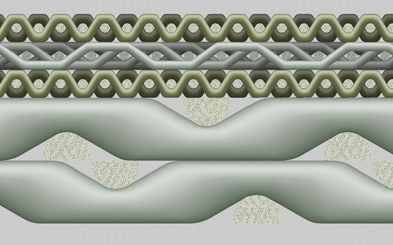
Top view of a five-layer sintered wire mesh example. The layer arrangement shown is illustrative, not the structure of every element.
Cross-section of a five-layer sintered wire mesh example showing filtration and support layers.
Original specification tables
The three existing specification tables below remain as published product reference data. Please specify the model and measurement conditions when requesting a confirmed element specification; figures from a material table must not be treated automatically as finished-cartridge performance.
Standard Sintered Wire Mesh Data Sheet of Five-Layer Sintered Mesh
Model
Nominal Rating
Structure
Thickness
Air Permeability
Bubble Point Pressure
μm
mm
l/min/cm2
mmH20
SMF5-1
1
200+400×3000+200+12×64+64×12
1.7
1.81
360-600
SMF5-2
2
100+325×2300+100+12×64+64×12
1.7
2.35
300-590
SMF5-5
5
100+200×1400+100+12×64+64×12
1.7
2.42
260-550
SMF5-10
10
100+165×1400+100+12×64+64×12
1.7
3
220-500
SMF5-15
15
100+165×1200+100+12×64+64×12
1.7
3.41
200-480
SMF5-20
20
100+165×800+100+12×64+64×12
1.7
4.5
170-450
SMF5-25
25
100+165×600+100+12×64+64×12
1.7
6.12
150-410
SMF5-30
30
100+400+100+12×64+64×12
1.7
6.7
120-390
SMF5-40
40
100+325+100+12×64+64×12
1.7
6.86
100-350
SMF5-50
50
100+250+100+12×64+64×12
1.7
8.41
90-300
SMF-75
75
100+200+100+12×64+64×12
1.7
8.7
80-250
SMF5-100
100
100+150+100+12×64+64×12
1.7
9.1
70-190
Note: Weight kg/m2, 5 layers sintered 8.4kg; 6 layers sintered 14.4kg
6 layers sintered mesh with another layer of 12 mesh to resist high pressure. Thichkess reaches 3.5mm
Data Sheet of 2-7 Layers Sintered Wire Cloth
Item
Filter rating(um)
Structure (mesh /inch)
Thickness
(mm)
Porosity (%)
Weight
(kg/m2)
SMF2-T0.5
2-100
Filter layer+60
0.5
60
1.6
SMF3-T0.7
2-100
60 +Filter layer+60
0.7
56
2.4
SMF3-T1.0
2-200
50 +Filter layer+20
1.0
58
3.3
SMF3-T2.0
2-200
Filter layer+20+8
2.0
58
6.5
SMF4-T1.0
2-200
60+Filter layer+40+20
1.0
45
4.4
SMF4-T1.7
2-200
40 +Filter layer +20 +16
1.7
55
6.2
SMF5-T1.9
2-200
30 +Filter layer+ 60 +20 +16
1.9
52
5.3
SMF5-T2.5
2-200
80 +Filter layer +30 +10 +8
2.5
55
8.8
SMF7-T2.0
2-200
50 +filter layer+ 40 +20 +40 +filter layer+50
2.0
58
7.4
Note: 1. Filter layer could be customized according to your demand.
Other layer structures could be adjusted based on your specific requirement.
Technical Data Sheet of Sintered wire cloth and Perforeated Plate
Model
Filter Rating
(μm)
Structure
Thickness
(mm)
Weight
(kg/m²)
Porosity
(%)
SMF-T2
2-200
30 +filter layer +30 +D4×P5×T1.0
2
6.7
57
SMF-T2.5
2-200
30 +filter layer +30 +D5×P7×T1.5
2.5
9.8
50
SMF5-T3
2-200
60 +filter layer +60 +20 +D6×P8×T2.0
3
11.9
50
SMF5-T3.5
2-200
20 +filter layer +20 +10 +D8×P10×T2.0
3.5
12.6
54
SMF5-T4.0
2-200
20 +filter layer +20 +10 +D8×P10×T2.5
4
14.2
55
SMF5-T4.3
2-200
20 +filter layer +20 +10+D10×P13×T3.0
4.3
16.8
50
SMF5-T5.3
2-200
20 +filter layer +20 +10+D10×P13×T3.0
5.3
20.6
51
Note: Other structures could also be customized
It’s suitable for higher differential pressure drop application.
Manufacturing Process Illustrations
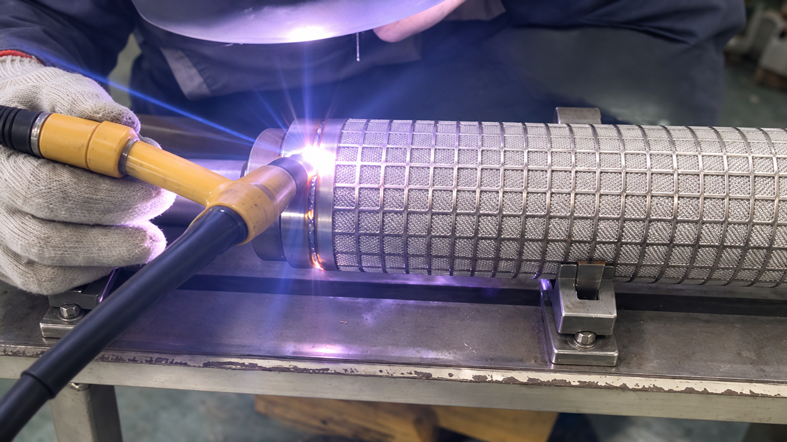
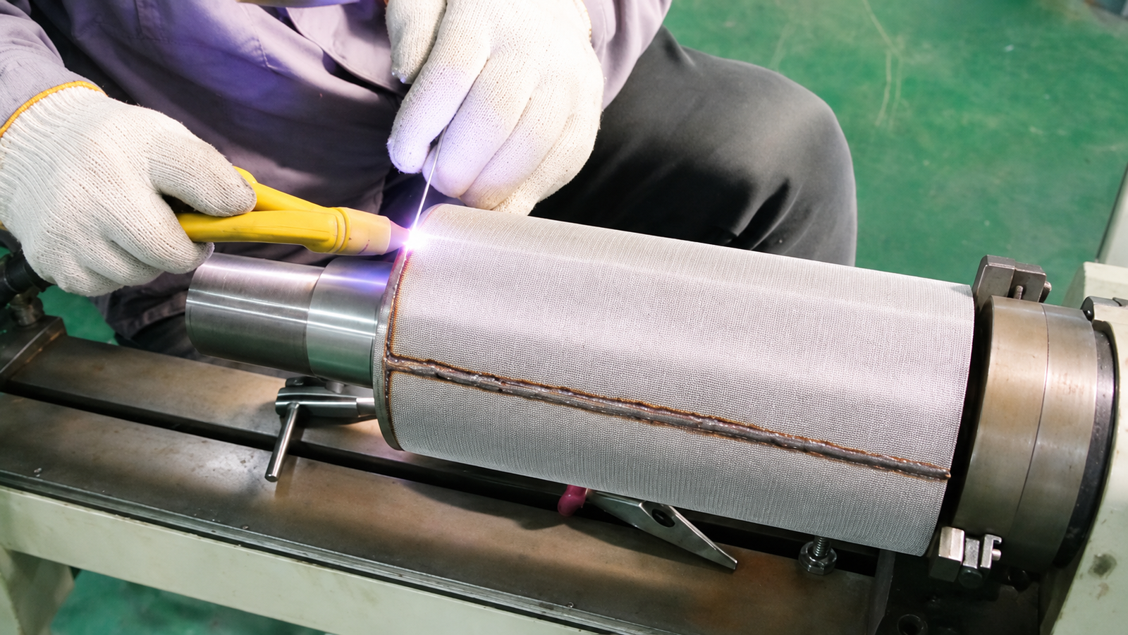
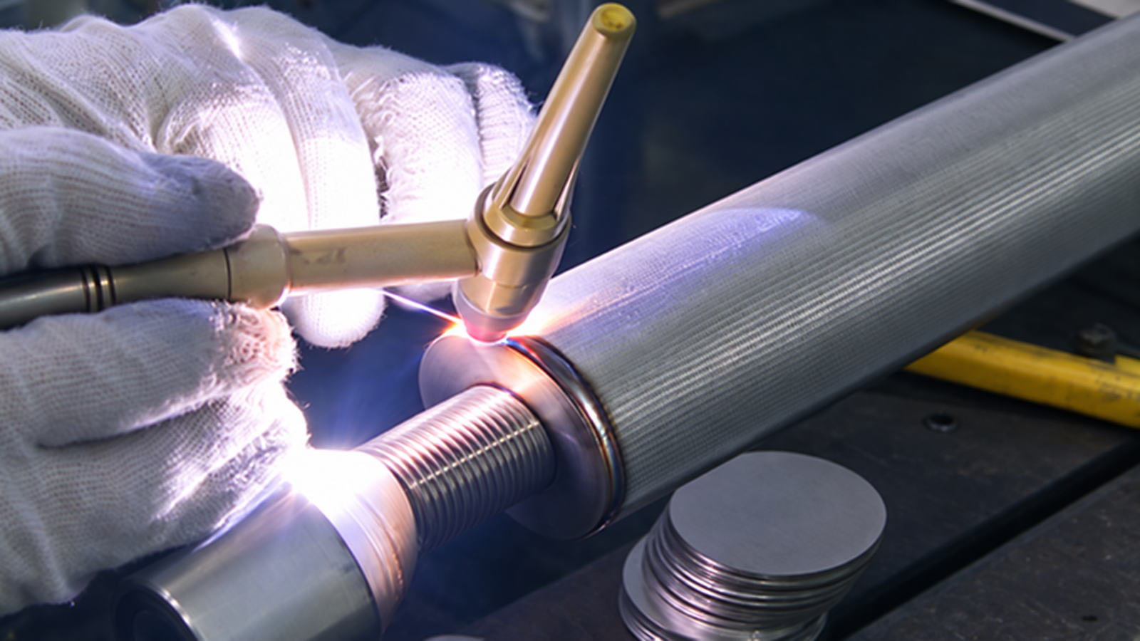
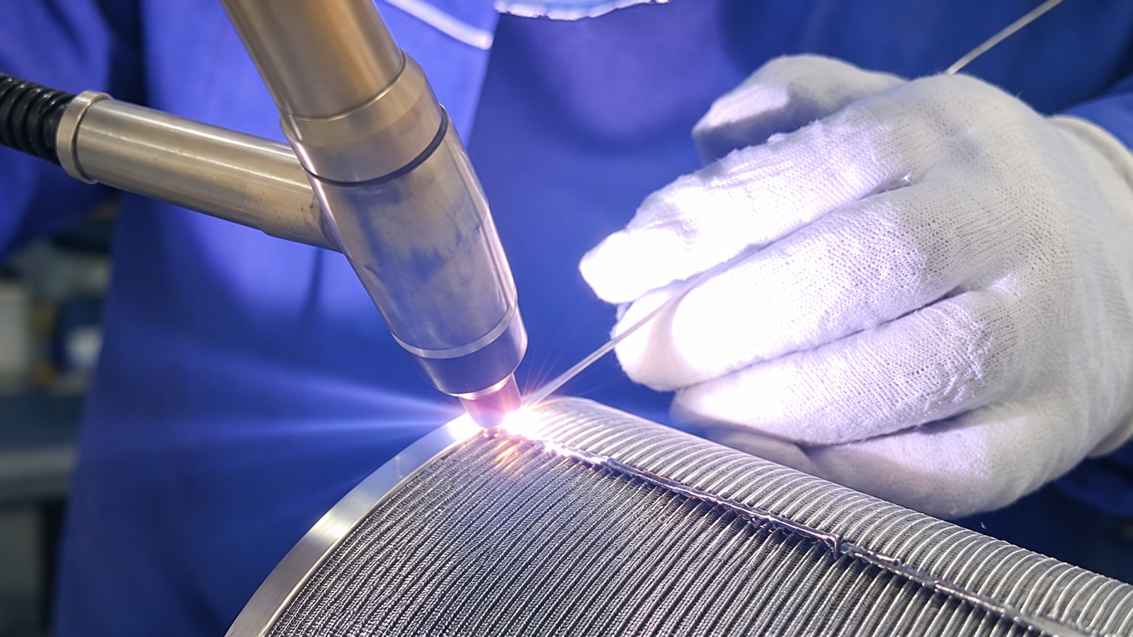
These process illustrations show joining steps for cylindrical metal mesh filter elements. Weld placement and connection geometry are reviewed against the finished-element drawing; the images do not establish a filtration rating or weld qualification.
End-ring welding on a cylindrical sintered mesh filter element.
Longitudinal seam welding on a metal mesh filter cylinder.
Threaded end fitting welded to a cylindrical sintered mesh filter.
Close-up seam welding on a curved metal mesh filter cylinder.
SMF-1: Round sintered mesh filter discs; choose mesh and dimensions for the required duty.
SMF-2: Shaped sintered mesh panel; confirm material and cut geometry against the drawing.
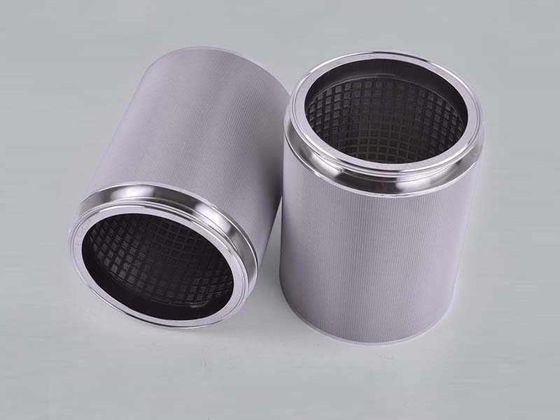
SMF-3: Cylindrical sintered mesh element with an outer fine mesh layer.
SMF-4: Laminated sintered mesh tube. Rating and application are confirmed per order.
SMF-5: Cylindrical sintered mesh element with a supported structure.
SMF-6: Sintered mesh element with perforated support layer.
SMF-7: Sintered mesh element shown with a cleaning-related assembly; cleaning performance requires a defined system.
SMF-8: The sintered metal filter elements in three different sizes together used as gas turbine oil filter
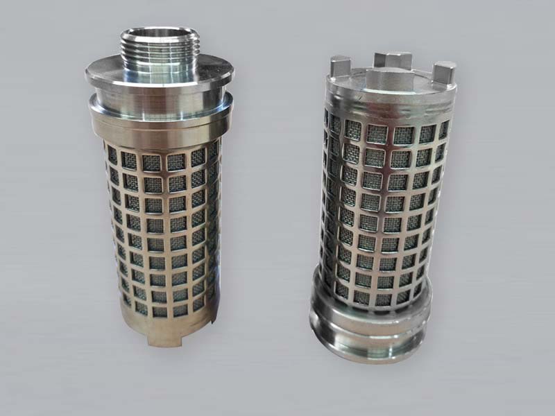
SMF-9: Cylindrical sintered mesh filter with long male threaded connection.
SMF-10: Sintered mesh filter element with short male threaded connection.
SMF-11: Sintered mesh filter elements with hexagonal connectors
SMF-12: Sintered mesh filter element with perforated support structure.
Manufacturing and inspection
After confirming the mesh structure and element drawing, the material is formed or cut and joined to the required ends, supports or connections. Inspection focuses on dimensions, surface condition, cut edges, welds, fittings and sealing faces.
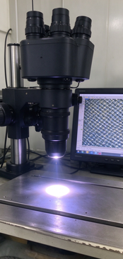
The microscope image at right shows one inspection method. If a project specifies flow, permeability, bubble point or retention testing, the sample, method and test conditions should be agreed in advance. This photograph alone does not establish filtration rating.
Information to send with an inquiry
Drawing or photograph of the existing element
Material and process medium
Normal and peak temperature
Target particle size or rating, and required test method
Flow rate and allowable pressure drop
Element dimensions, sealing faces and connections
Cleaning method
Quantity
If replacing a failed element: clogging, deformation, leakage or shortened service life
Microscope and screen used to examine a mesh surface; the image alone does not establish filtration rating.
Frequently asked questions
Can a disc rating be used as the guaranteed rating of a finished cartridge?
Not automatically. Define the medium, construction and test method before comparing finished elements.
Can you work from an existing cartridge?
Yes. A drawing, sample or clear dimensions can support an assessment of the mating geometry and construction.
Can the element be backwashed and reused?
That depends on the structure, pressure direction, contamination and cleaning medium. Confirm the procedure and inspect the element after cleaning.
How do I select material and mesh rating?
Provide the process medium, temperature, particle target, flow and allowable pressure drop. Material name or mesh count alone is insufficient.
Discuss Your Filtration Requirements
Choose the path that matches your project:
Custom Design for a New Project
For a new filtration application, discuss the operating conditions and required finished product with us. Provide the process medium and particles, target filtration rating and test method, flow, temperature, pressure, allowable pressure drop, installation space and cleaning method. We can work through the sintered mesh layer structure, material, element shape, support and connections, then agree on drawings, samples and checks before production.
Build to Drawing for Replacement
To replace an existing filter element when you have drawings or specification data, send the drawings, dimensions and tolerances, material, filtration rating, layer structure if specified, connections and relevant operating conditions. We will review the requirements and manufacture the replacement to the agreed drawing and specification.
Recreate from an Existing Sample
If you have no drawing or complete data, send us an existing filter element. We can measure its dimensions, inspect its mesh construction, support and connections, and document the specifications that can be recovered. We will confirm any uncertain material or performance requirements with you before reproducing the element; a used sample alone may not establish its original filtration rating.