Match the pattern
Select the same hole shape and row arrangement shown on the approved drawing or sample.

Engineering Tool · Perforated Metal
Calculate theoretical open area for common round, square, hexagonal, slotted and rectangular perforation patterns from opening dimensions and centre-to-centre pitch.
Quick definition: open area is the percentage of a repeating sheet surface occupied by holes. It is a geometric value—not a direct prediction of flow rate, pressure drop or filtration efficiency.
Choose the pattern shown on your drawing, then enter dimensions in one consistent unit.
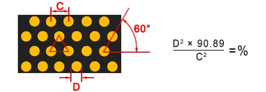
The densest standard round-hole layout. Pitch is measured centre to centre.
Theoretical values for one repeating pattern cell.
OA = 90.69 × (D ÷ C)²D = hole diameter; C = equal centre pitch. Use the same unit for both.
Use actual dimensions of a flat rectangular sheet to estimate open area after blank margins and a weld strip.
Use the hole pattern above. Then select the boundary layout below and enter the finished sheet dimensions.
Enter actual sheet, margin and weld-strip dimensions in mm, matching the unit selected above. The strip is subtracted within the area left after the margins.
Select a boundary layout to continue.
Overall open area = pattern open area × perforated region ÷ gross sheet area. This geometric estimate assumes a uniform pattern in the remaining region; partial edge rows, forming and supports are not modeled.
Select the same hole shape and row arrangement shown on the approved drawing or sample.
Enter centre-to-centre spacing, not the solid ligament between adjacent hole edges.
Account for blank margins, seams, forming zones, supports and tolerances before using the result for design.
The calculator evaluates one ideal repeating pattern cell. Round, square and rectangular openings use geometric opening area divided by the associated pitch cell. Round-end slots use the area of the straight centre section plus two semicircular ends.
For the hexagonal mode, S and C must follow the dimensions in the displayed diagram. If your drawing defines a hexagon by side length, across-corners distance or another pitch convention, calculate from the actual repeating cell area instead.
Do not treat theoretical open area as usable flow area for a finished component. Unperforated borders, welds, overlaps, reinforcing rings, supporting mesh, blocked surfaces and formed sections can reduce the active area.
The calculator is not intended for louvres, bridge slots, countersunk holes, embossed or raised holes, decorative irregular patterns, variable pitch, nested patterns or damaged/distorted perforations.
| Pattern | Formula | Required dimensions | Important condition |
|---|---|---|---|
| Round, 60° staggered | OA = 90.69(D/C)² | D, equal pitch C | C must exceed D |
| Round, straight | OA = 78.54D²/(C1C2) | D, C1, C2 | Use centre pitches |
| Square or rectangular | OA = 100WL/(C1C2) | W, L, C1, C2 | Opening must fit the pitch cell |
| Round-end slot | OA = 100[W(L−W)+πW²/4]/(C1C2) | Overall L, W, C1, C2 | L must be at least W |
| Hexagonal diagram mode | OA = 100(S/C)² | Diagram-defined S and C | Do not substitute side length |
It is the percentage of an ideal repeating sheet area occupied by holes. It describes geometry, not filtration efficiency or guaranteed airflow.
The triangular repeating layout packs equal round holes more closely than a straight square layout at the same diameter and pitch.
No. Pitch is measured from the centre of one opening to the centre of the next. Ligament is the solid edge-to-edge distance.
Not in this two-dimensional formula. Thickness can affect punching feasibility, hole taper, burrs, pressure loss and finished performance, but not the nominal surface ratio.
No. Flow and separation performance also depend on thickness, hole geometry, fluid properties, pressure, edge conditions, downstream supports and system design.
Blank margins, weld bands, overlaps, frames, supports and blocked surfaces remain solid or obstructed, reducing the actual active area.
No. Use them for preliminary engineering selection. Final tolerances and usable area should be confirmed on approved drawings and inspected parts.
Share the hole pattern, dimensions, material, thickness, margins and drawing with our engineers.
Engineering disclaimer: Results are theoretical estimates for preliminary selection and do not constitute a performance guarantee or final design. Critical applications require approved drawings, manufacturing feasibility review and inspection of the finished component.
