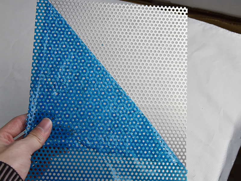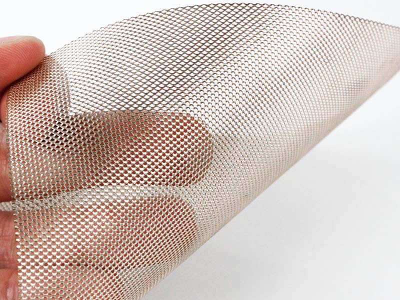
Etched Metal Filters & Photo Etched Mesh
Filtalloy supplies photochemically etched metal filters and photo etched mesh as discs, sheets, screen plates, formed cylinders and welded assemblies. Hole patterns and outlines are developed from your drawing.
Standard material thickness is 0.1–1 mm and regular processing sheet size is 600 × 1500 mm. Send the drawing or pattern and quantity to review material, aperture and dimensional requirements.
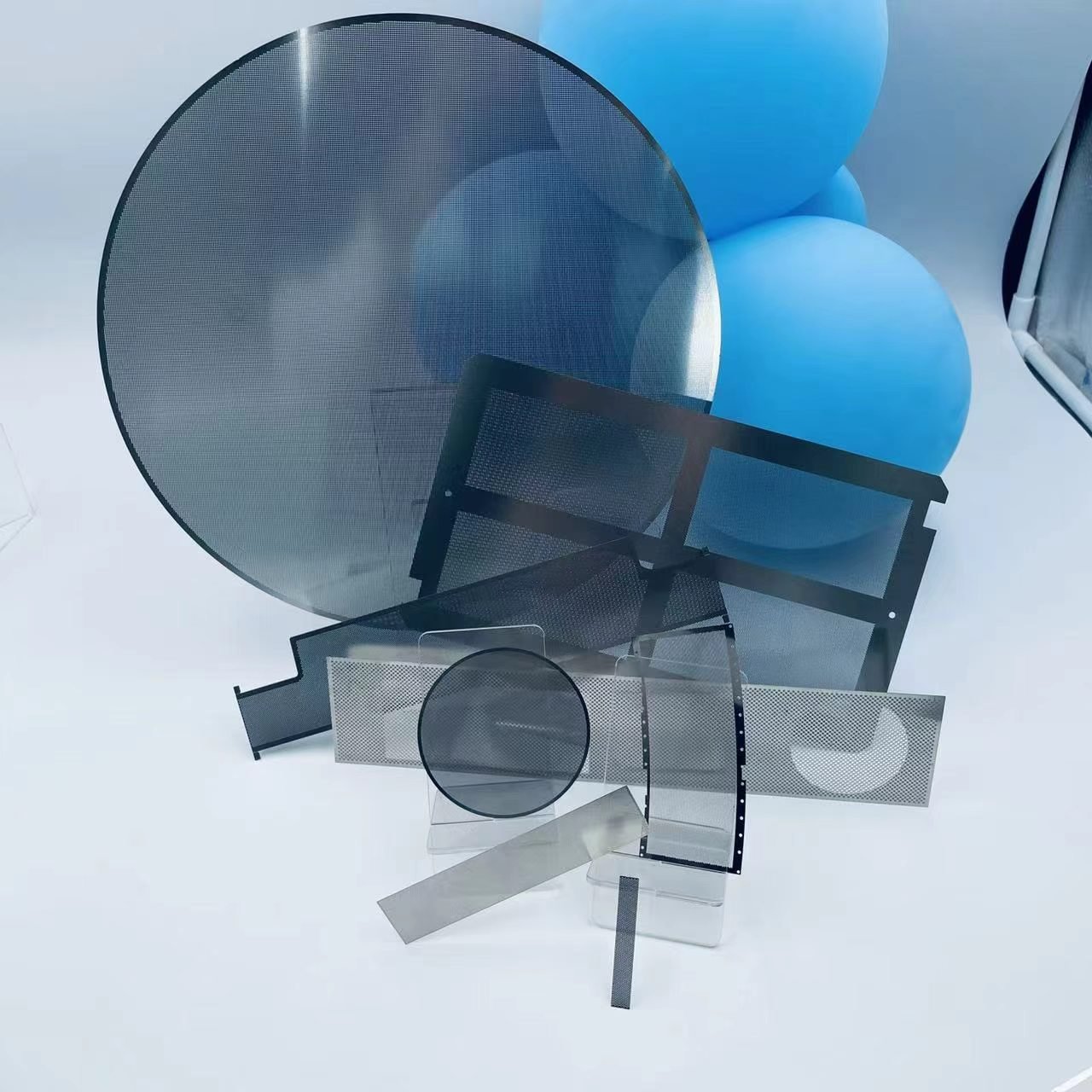
Supply Forms and Product Configurations
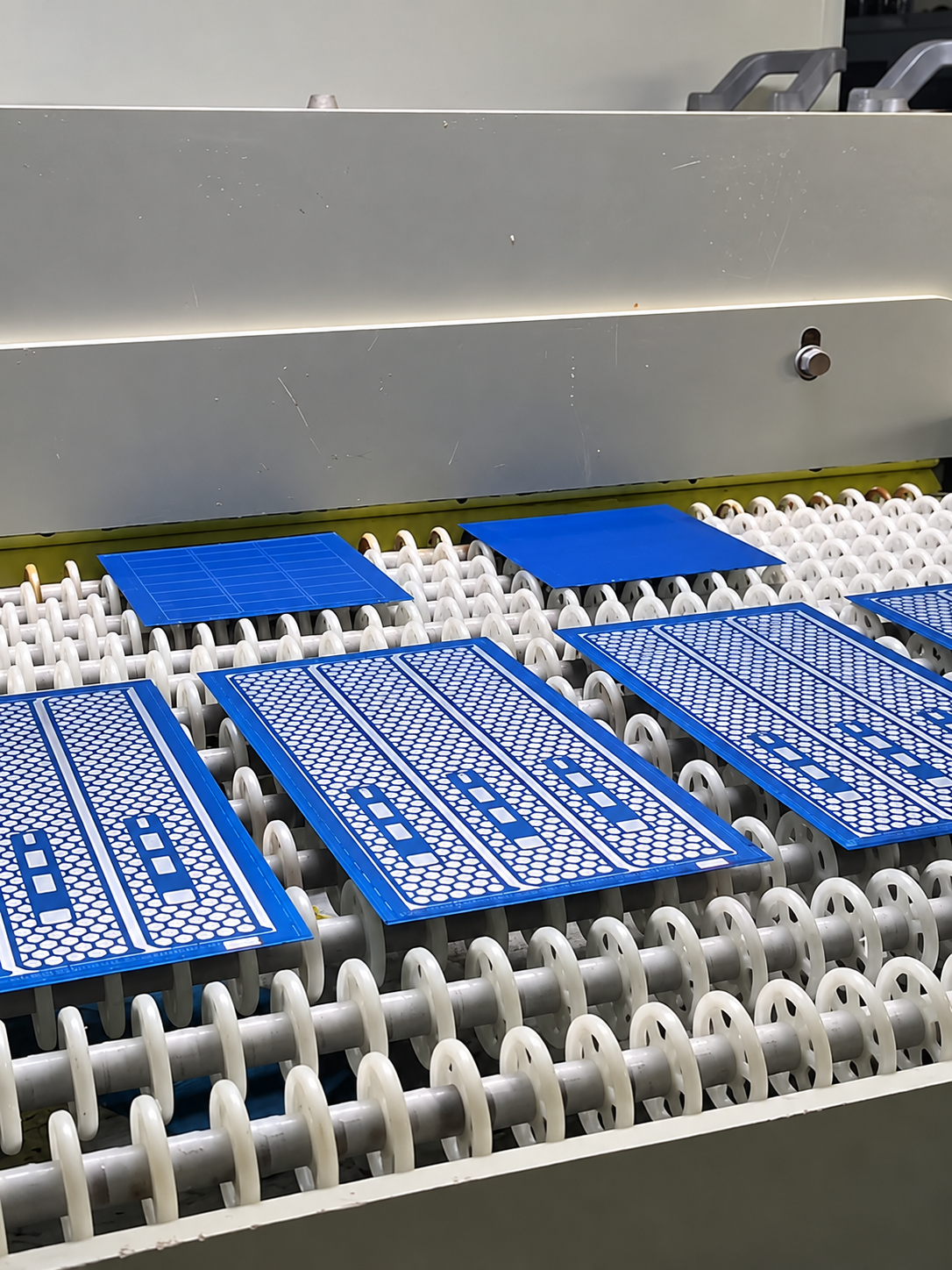
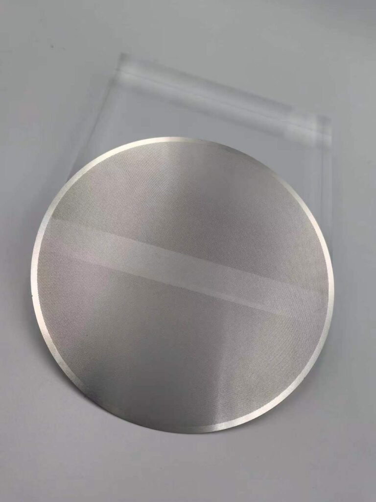
The views below show product forms and construction details. Send the drawing or existing specification for the configuration you need.
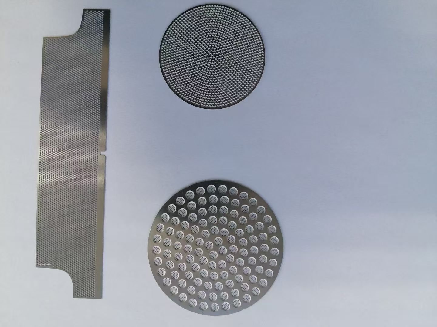
Etched Metal Filter Specifications
| Item | Available specification |
|---|---|
| Process | Photochemical etching (PCM / chemical etching) |
| Materials | Stainless steel 304, 310, 316L and 430; steel; copper; brass; phosphor bronze; titanium; nickel alloys |
| Thickness | 0.1–1 mm; common options include 0.1, 0.12, 0.15, 0.2 and 0.3 mm |
| Sheet size | Regular processing format: 600 × 1500 mm |
| Hole shapes | Round, square, long slots and custom shapes |
| Part outlines | Discs, rectangles, kidney shapes and drawing-defined profiles |
| Supply forms | Filter sheets and discs, screen plates, formed filter cylinders and welded assemblies |
| Tolerances | Agreed according to the customer drawing |
| Packing | Protective film or bags, cushioning, and cartons or wooden cases as appropriate |
Use the sheet format to plan nesting, and specify the finished dimensions of each part separately. Parts may be nested on a sheet and separated after processing. Each flat etched filter pattern is made without splicing; formed cylinders and welded assemblies have joints defined by their assembly drawing.
Why choose photo etched filters?
- Round holes, square holes, long slots and custom apertures in one sheet.
- One-piece etched filter patterns without spliced sheet sections.
- No cutting tool contact or laser cutting heat-affected zone during etching.
- Etched edges without the punching burrs associated with mechanical perforation.
- Design changes through updated phototools rather than hard punching dies.
- Multiple parts nested on a processing sheet for efficient batch production.
Minimum Hole Size and Design Guidelines
For regular designs, we recommend a minimum hole diameter of 1.1–1.2 times the sheet thickness. The metal ligament between holes (bar width) should generally be at least the sheet thickness. Thicker sheets therefore require larger apertures and wider ligaments.
0.1 mm (100 μm) through holes are available for batch production in suitable thin-sheet designs, subject to material and pattern review. This is not a minimum guaranteed across the full 0.1–1 mm thickness range. For example, a 0.5 mm sheet would normally start with a recommended minimum hole diameter of approximately 0.55–0.60 mm.
Etching removes metal sideways as well as through the thickness. This undercut affects hole profile and ligament width, so artwork compensation and drawing review are needed. Dimensions, hole positions, flatness and acceptance tolerances are agreed on the customer drawing.
Use the photo-etched filter design guide to review hole size, sheet thickness, ligament width, measurement plane and drawing tolerances together.
How Photochemical Etching Works
Photochemical etching, also called photochemical machining (PCM), transfers a pattern onto photoresist-coated metal using UV exposure. Developing reveals the areas to be removed, and a controlled etchant selectively dissolves the exposed metal. Double-sided etching removes material from both faces to form through apertures.
- Drawing and DFM review: assess material, thickness, aperture size, ligament width and tolerances.
- Blank preparation and cleaning: cut the sheet and remove oil and surface contamination.
- Photoresist coating: apply and dry the resist on both sides.
- UV exposure: transfer the phototool pattern to the resist.
- Developing: reveal the metal areas selected for etching.
- Controlled etching: dissolve exposed metal to create the required pattern.
- Stripping, cleaning and drying: remove remaining resist and processing residues.
Etching avoids the mechanical cutting forces of punching and the local thermal cutting zone of a laser. Temperature and chemistry are controlled throughout the process.
Drawing and delivery records
Use the existing drawing as the starting point and clarify only missing details relevant to the part.
| Record group | Details to agree |
|---|---|
| Supply form and edges | Identify a nested sheet or separated parts, solid borders, mounting holes, weld lands and any bridge/tag positions. Agree separation and remaining edge condition on the drawing. |
| Geometric inspection | Identify each observed face, sheet thickness, hole-mouth or agreed minimum-channel dimension, ligament width, hole position, outline and flatness state. Keep the method, sampling and acceptance requirement with the result. |
| Filtration requirement | Record the dimensional object and measuring face separately from the grade definition. If retention performance is required, attach the agreed test conditions and result rather than deriving it from hole diameter. |
Use backlighting to check through-hole condition. For dimensional acceptance, record the measuring method, sampling and agreed tolerance alongside the result; identify instrument resolution as one part of that measurement record. See the micron rating and efficiency guide for geometry versus particle-removal performance. Identify bridge locations, removal and the required remaining edge condition during drawing review, so separation and finishing match the delivered part.
Through-Hole and Functional Inspection
Backlight inspection checks for blocked holes, incomplete through etching and local residual material or resist. A permeability / flow test bench is available to assess functional flow behaviour under agreed test conditions.
Inspection scope, sampling and acceptance criteria are established for the order. Specify the test medium, pressure or pressure differential, fixture and target flow where functional testing is needed. Use hole diameter and open area to describe geometry and assess flow. Where particle retention is required, agree the performance definition and test conditions for that application.
Material certificates, dimensional inspection records and any third-party testing requirements should be requested during project review so availability and scope can be confirmed.
Applications of Photo Etched Mesh
Custom etched metal filters can be specified for particle screening, liquid filtration, flow distribution and airflow control. Typical uses include industrial filter components, coffee and juice filter parts, intake and diffuser screens, laboratory screening parts, and fine screens for plastic or fibre processing.
Nickel etched screens may also be developed for electrolysis-related components. Material compatibility, flow behaviour and the role of the component must be evaluated for the specific system. Aperture size alone does not establish a filtration rating or electrochemical performance.
For other construction methods, explore our perforated sheets, expanded mesh and nickel wire mesh.
Cleaning, Forming and Assembly
Etched sheets can be supplied as flat filter parts or developed into formed filter cylinders and welded assemblies. Cleaning, flattening, forming, welding and surface treatment can be coordinated for the project. The finishing method and inspection requirements are agreed during drawing review.
Photochemical etching is best suited to thin-sheet parts. Increasing thickness increases undercut and restricts small features. It does not replace machining for deep holes or complex three-dimensional structures. Thin components also require careful handling to control flatness.
Send Your Drawing, Specification or Sample Photos
Send the drawing or existing specification you have, together with the quantity and the parts you need. Sample photos and main dimensions are a useful starting point when a drawing is unavailable.
If you are still defining the product, briefly describe its intended use. We will clarify the additional manufacturing and inspection details with you.