An etched filter drawing should relate material and thickness, opening pattern and pitch, remaining ligament width, the location of hole dimensions, and the delivery condition. A hole diameter alone does not fully describe a thin metal screen, and a tolerance alone does not identify the surface or section it controls.
Start with the drawing you already have. This guide explains how the fields relate so you can retain confirmed requirements and clarify the gaps that affect manufacturing and inspection.
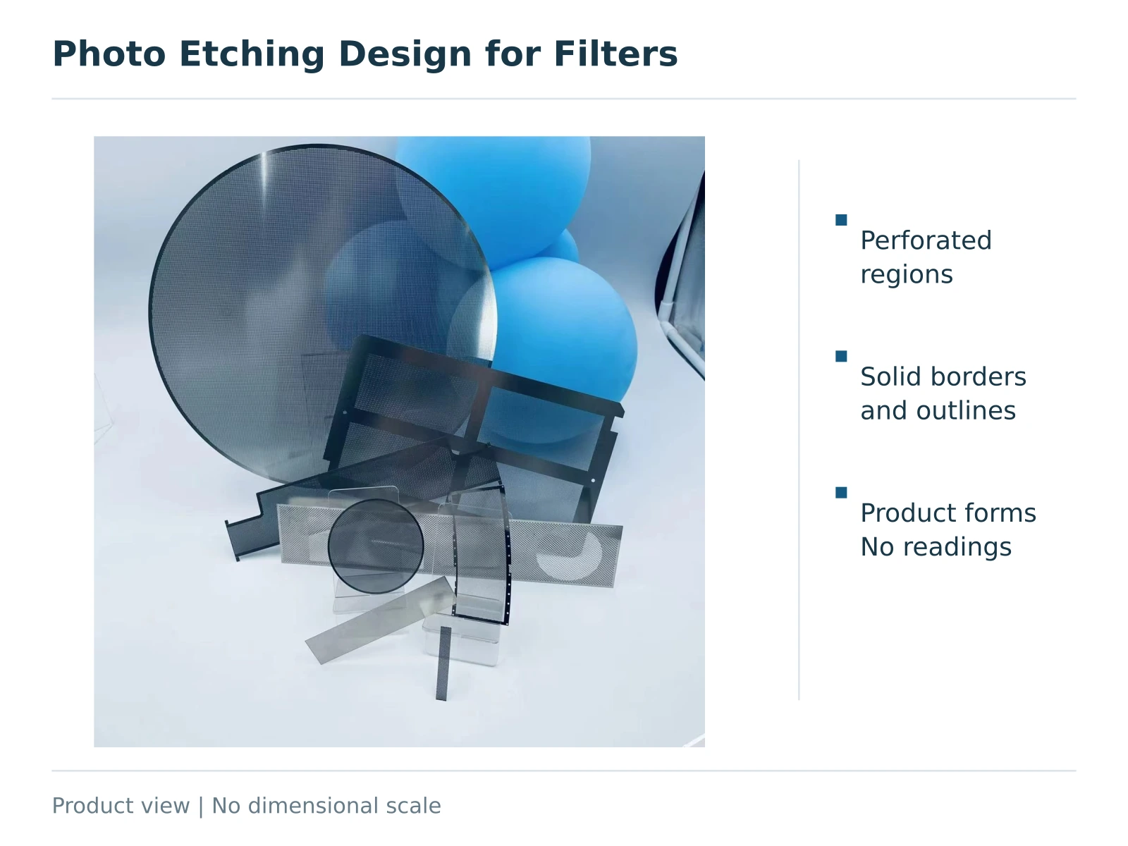
1. Design Parameter Review
Define each dimension before deciding whether the dimensions can be produced together. Photochemical machining uses a resist pattern to protect retained regions while exposed metal is etched away. The public abstract of the ASM Handbook chapter identifies dimensional limitations, tolerances and edge quality among its design considerations [1].
| Parameter group | What to identify | Ambiguity to avoid |
|---|---|---|
| Material and thickness | Grade, nominal thickness and thickness requirement | Treating different materials or thicknesses as one design |
| Opening geometry | Round, slot or custom shape; dimensional location | Treating a surface opening as the whole passage |
| Pitch and ligament | Hole-centre arrangement and retained metal | Changing holes without checking remaining ligaments |
| Outline and border | Finished outline, unperforated areas, mounting holes and references | Confusing processing sheet format with finished size |
| Delivery and inspection | Panelled or separated; flat or formed; critical tolerances | Inspecting different manufacturing states |
Do not recreate information already defined in the approved drawing. If it includes a filtration rating, state whether that means a geometric opening or a particle-removal grade established by a test. Dimensions and performance may both be specified, but do not replace each other. See our micron rating and efficiency guide.
2. Thickness, Hole Diameter and Ligament Width
Hole size describes removed regions, ligament width describes retained metal, and thickness affects the conditions for producing both.
Recheck holes and ligaments when thickness changes
Etching removes metal through the sheet and can also remove material laterally beneath resist edges. This undercut connects through-etching to edge geometry. The Open University's design explanation relates undercut to hole profile and identifies material, thickness and image design as factors affecting dimensions and tolerances [2]. A small opening established for one thin-sheet design cannot simply be extended across all thicknesses.
If a design becomes thicker while keeping the same small holes and narrow ligaments, review through-etching, hole profile and retained metal together. Reducing thickness also does not automatically resolve every constraint: handling, clamping, forming and support may need review.
Use a general ratio for initial screening, then review the actual material, pattern and thickness together and define how the critical features will be verified.
Pitch and ligament are different dimensions
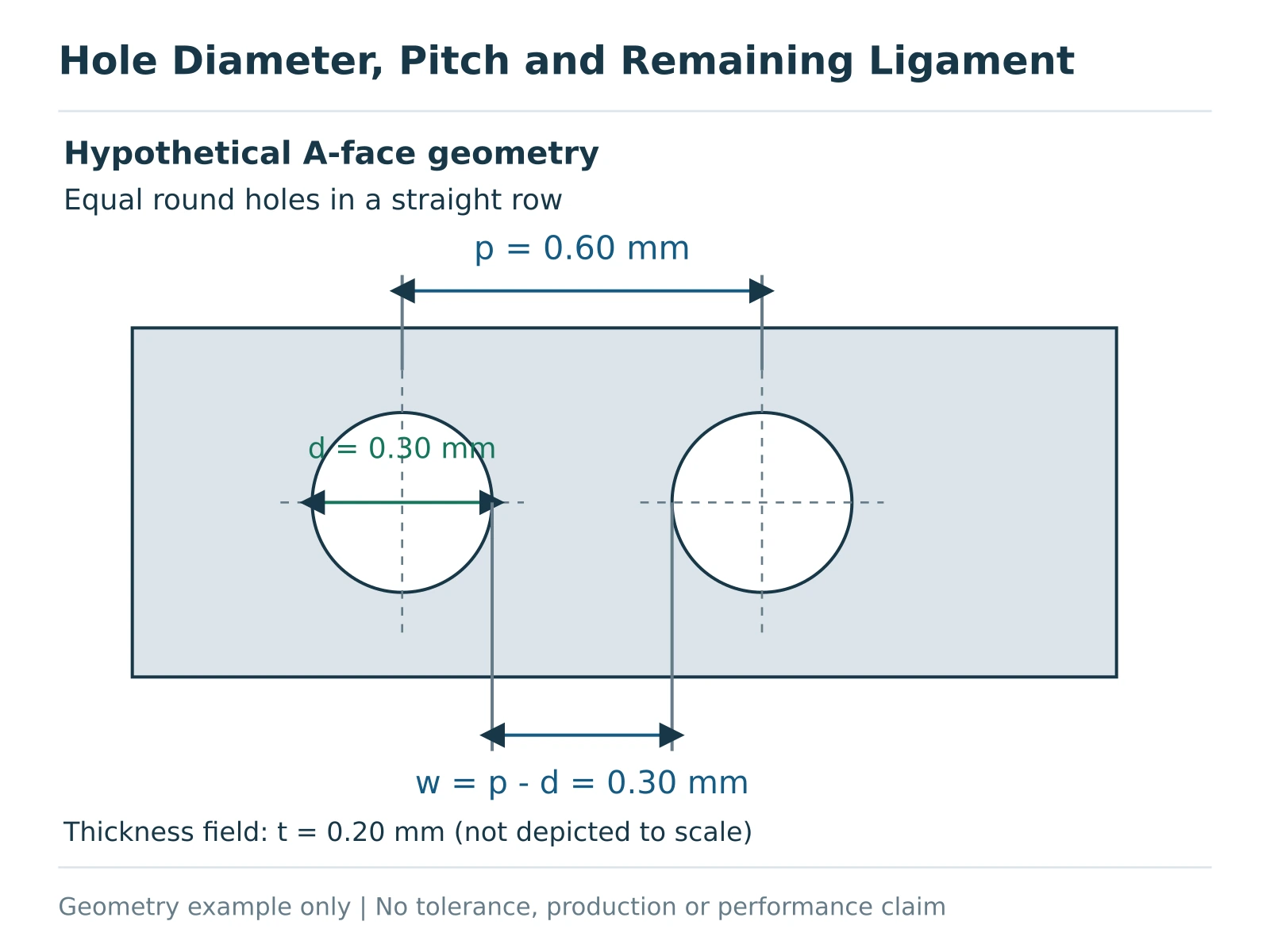
Pitch generally describes hole-centre spacing. Ligament width describes the metal between openings. Their relationship requires a defined hole shape, arrangement, direction and measurement plane.
For equal round holes in a straight, equally spaced row, measured in the same plane along the line joining adjacent centres:
Ligament width w = centre pitch p − hole diameter d.
Use consistent units and the same plane for d and w. This is a simple geometric identity, not an etching-capability equation. Staggered arrays, slots, custom shapes and changing hole profiles require their actual neighbouring boundaries to be checked. Inspect local narrow regions near corners, mounting holes and custom outlines as well as the main dimension chain.
Keep the purpose of a design change
If a larger opening is requested, distinguish a change in individual hole size, planar open area or functional flow. These are related but different aims.
At fixed pitch in the simple round-hole example, increasing diameter reduces the remaining ligament along the centre line. Increasing pitch as well changes the number and coverage of openings. Record which dimensions may change and which must remain fixed so manufacturing review does not optimise an isolated number.
3. Hole Profiles and Measurement Faces
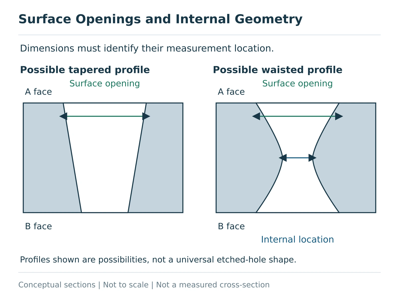
Tie a hole dimension to a defined location. Do not assume the surface opening equals the narrowest internal section. Etched walls may be tapered, curved or locally constricted. Meeting regions in double-sided etching also affect the profile. Neither straight walls nor one universal “hourglass” shape should be assumed for every etched hole.
| Dimensional object | Drawing description | Evidence to retain |
|---|---|---|
| Face A opening | Identify face A and observation direction | Method, boundary interpretation and surface condition |
| Face B opening | Define separately, or explicitly state equality | Consistent face references |
| Internal passage or narrowest section | Define when function requires it | A method capable of verifying that location |
If a drawing says “diameter d,” clarify whether d means an opening on a specified face or a separately defined section. This gives inspection a repeatable boundary to examine.
A front-view optical observation can describe the visible boundary but may not reveal the complete wall. Backlighting checks through-opening condition; it does not alone prove both face diameters, the narrowest section and hole position. Where internal geometry matters, agree an appropriate method, potentially a suitable section examination, and record any destructive sample requirement.
Separate finished dimensions from phototool compensation
The drawing should express the required finished geometry. Manufacturing compensation and verification support that target. Identify phototool dimensions or compensation values explicitly so they are not mistaken for finished acceptance dimensions. An unverified universal offset is not a substitute for reviewing hole size, outline and ligament features.
4. Solid Borders, Tabs and Delivery Condition
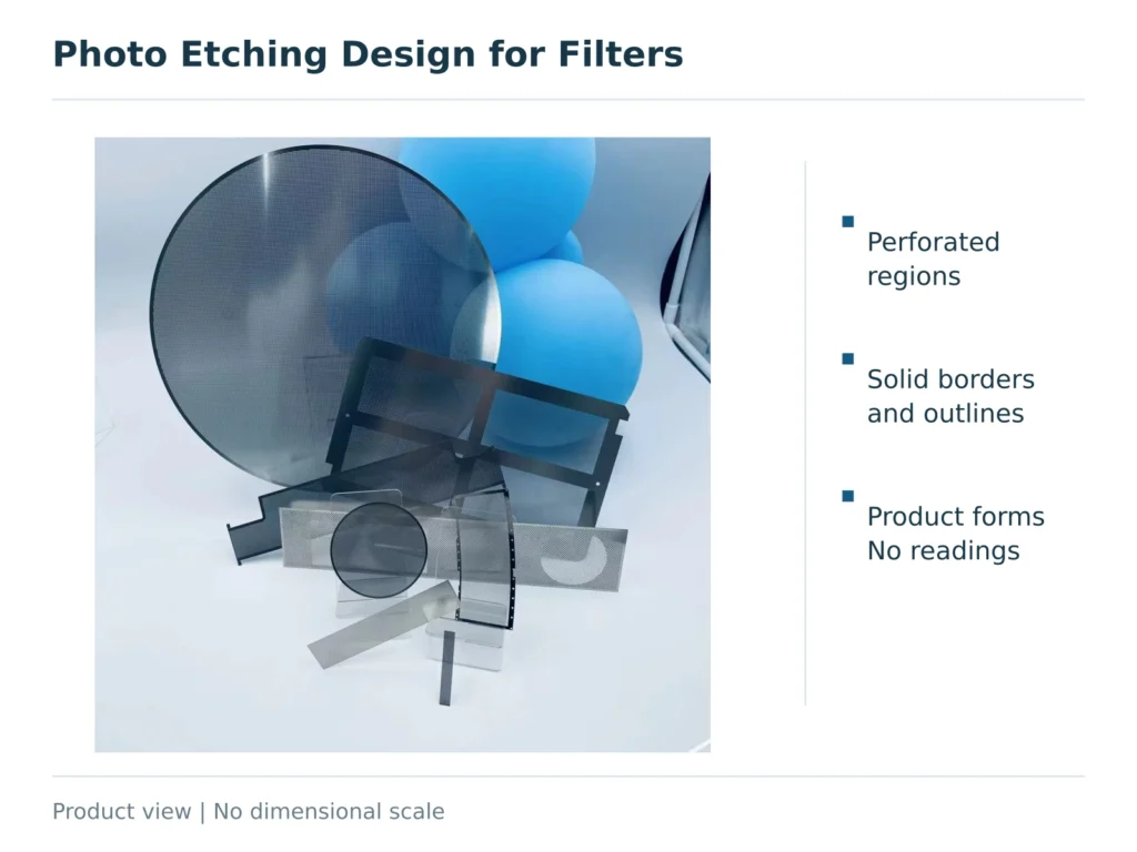
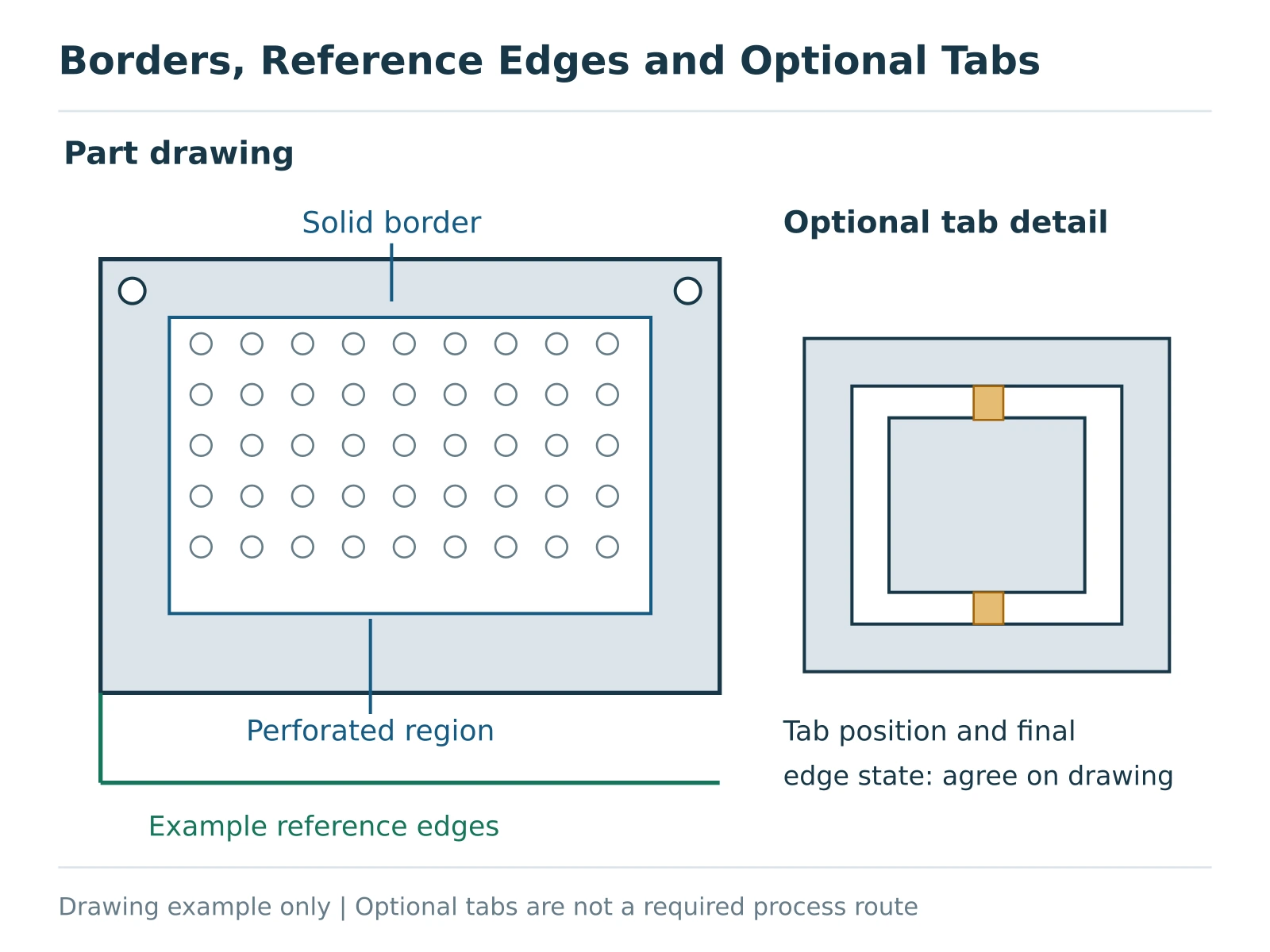
Metal outside the perforated region remains part of the functional drawing. Borders may provide mounting, clamping, sealing or welding areas. Locate the perforated region and unperforated bands relative to the outline and assembly references. A correctly sized pattern in the wrong position can still affect fit.
Panelled or separated parts
Parts may be delivered within a carrier panel or after separation. Where tabs retain parts, define their position, permitted locations and final edge state. Tabs are intentional connections. Separation marks, protrusions and permitted finishing need project-specific requirements; a general statement about etched edges does not resolve all delivery conditions.
Retain existing outline requirements. If tabs are not yet defined, identify assembly-critical and sealing edges first so acceptable locations can be reviewed.
Flat parts, formed parts and assemblies
For cylinders, cones or welded assemblies, distinguish flat-pattern dimensions from formed outlines, seams and assembly dimensions. A tolerance without an inspection stage may be applied to different states by different people.
Specify whether flatness is checked in the free state, on defined supports or in a particular fixture. Temporary flattening must not conceal a condition that was never agreed.
5. Critical Dimensions, Tolerances and Verification
Relate tolerances to function, dimensional objects, references and inspection state. Distinguish dimensions affecting fit or operation from general outline references. Mounting locations, sealing edges, weld lands, local ligaments and openings can have different roles and need not share one unexamined tolerance.
| Control object | Define together | Verification direction |
|---|---|---|
| Openings and ligaments | Face, location, dimensional meaning and allowed variation | Suitable optical or other geometry measurement |
| Hole and pattern position | References, orientation and location requirements | Coordinates or image measurement using the same references |
| Outline, edges and flatness | Separation/forming state and supports | Checks appropriate to that state |
| Functional behaviour | Medium, pressure differential, fixture and target | An agreed functional test |
Select the checks relevant to the drawing and agree the inspection scope, suitable equipment, sampling and acceptance rules for the order.
Instrument resolution alone does not prove a matching product tolerance. The method must suit the wall geometry, thin-part condition and boundary interpretation.
If a requested limit exceeds currently demonstrated verification conditions, review whether critical regions can be controlled separately, geometry can be adjusted or a sample is needed. Retain the functional objective and identify unverified requirements instead of issuing a blanket guarantee.
6. From a Geometric Example to a Reviewable Drawing
The following values are hypothetical geometry only, not factory measurements, a customer case or a capability commitment. Consider equal round openings in a straight, equally spaced row on face A.
| Field | Hypothetical value | Meaning |
|---|---|---|
| Sheet thickness t | 0.20 mm | Thickness field; material remains separately specified |
| Face A opening d | 0.30 mm | Face A mouth only, not every internal section |
| Adjacent centre pitch p | 0.60 mm | In the identified row direction |
| Centre-line ligament w | 0.30 mm | p − d in the same plane |
To turn this geometry into a production drawing, add face B and wall requirements, material, outline, borders, references, tolerances and delivery state. Specify any filtration rating, flow or load requirement separately with its verification method.
Review the drawing you have and fill only the missing information:
- Drawing identity: part number, revision, units and material.
- Functional pattern: hole shape, measurement face, arrangement, pitch and critical ligaments.
- Assembly relationship: outline, border, mounting holes, sealing or welding areas and references.
- Delivery condition: panelled or separated, tab locations, flat or formed assembly.
- Verification: critical dimensions, tolerances and measurement state; functional test conditions when required.
Start with the existing drawing and clarify the missing fields during review. If only a sample is available, include both faces, side and critical-detail photographs, and distinguish known dimensions from unknowns. See our etched metal filter page or contact our engineers about missing drawing information.
7. Frequently Asked Questions
Why review thickness when a product page lists a minimum hole size?
A minimum belongs to particular material, thickness and pattern conditions. It is not a guarantee across the complete supply range. Review through-etching, profile and retained ligament requirements for the actual drawing.
Does a compliant face A opening prove the whole hole complies?
It answers the face A requirement only. Face B, internal passage, position and through-opening requirements need their own relevant evidence where specified.
Do diameter and open area define the pattern?
Usually not. Define shape, arrangement and pitch or equivalent location information, and the plane and region used for open area. Be consistent about borders, mounting holes and other excluded areas.
Is the tightest tolerance on every dimension the safest approach?
First relate variation to function. A strict number without references, faces or state can still be ambiguous. Identify critical dimensions separately and agree general requirements for the rest.
Does compensation permit changing functional dimensions?
No. Keep the finished target separate from manufacturing compensation. A proposed change to finished diameter, ligament or another functional dimension requires a drawing-change decision rather than an assumed phototool adjustment.
References
- Howard Friedman, *Photochemical Machining*, ASM Handbook, Vol. 16, 1989, pp. 587–593. Public abstract used for definition and design scope only; the full chapter was not accessed and its numerical capability data are not reproduced. https://doi.org/10.31399/asm.hb.v16.a0002171
- The Open University, *Photochemical Machining (Photo-fabrication; Chemical milling)*, 2017. Used for basic relationships among undercut, profiles and dimensional conditions, not for factory recipes or tolerance commitments. https://www.open.edu/openlearn/science-maths-technology/engineering-technology/manupedia/photochemical-machining-photo-fabrication-chemical-milling
The review sequence, records and hypothetical example explain drawing communication; they are not a standard acceptance procedure or a test report.