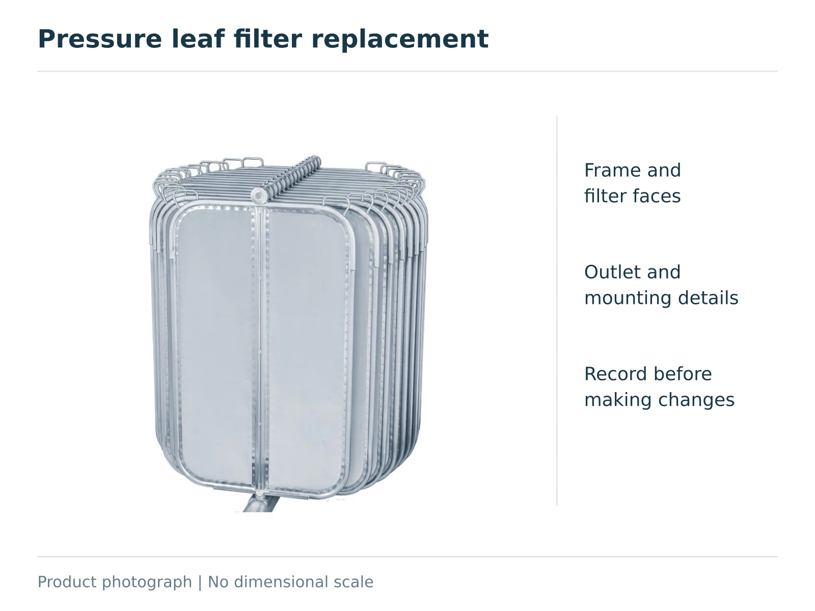
Pressure leaf filter replacement can start with an existing drawing or an old leaf. Record the outline and frame thickness, filtrate outlet position and connection, mounting and sealing interfaces, and the leaf arrangement inside the equipment. If a used leaf is distorted or damaged, separate its measured condition from the confirmed design requirements.
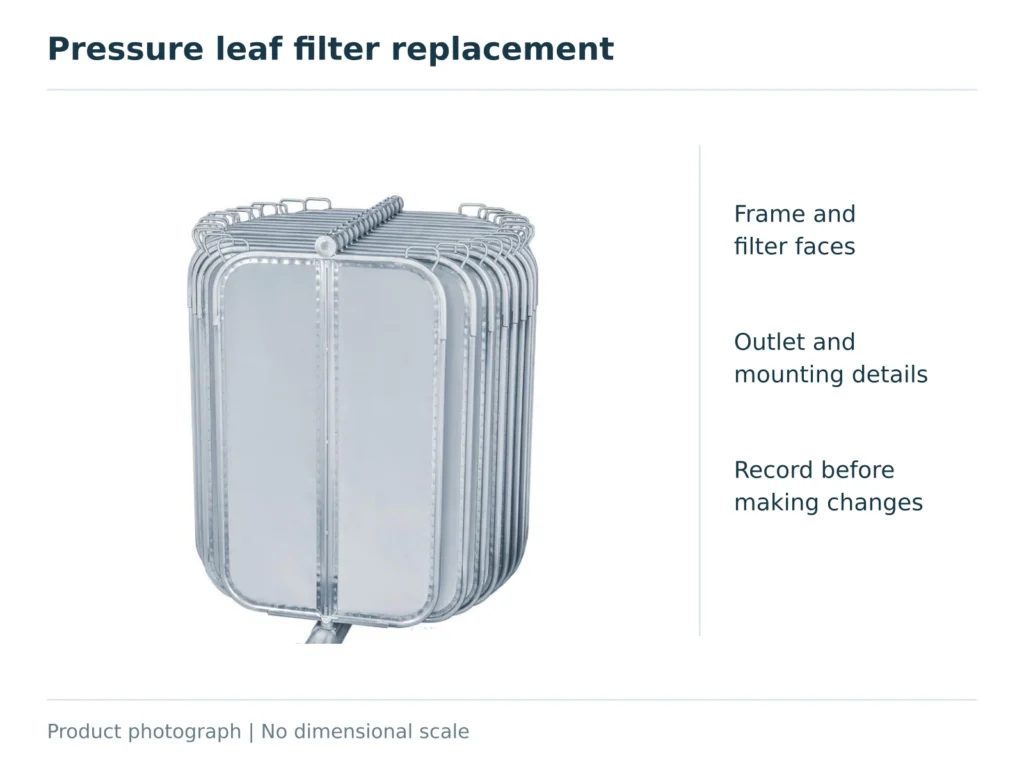
An overall photograph establishes the part's shape, but rarely explains its outlet, seals and internal construction. Keep the information already defined in your drawing and fill the gaps that affect manufacture and inspection.
1. Identify the sample and preserve its condition
Keep the connection between the sample and its equipment position before organizing dimensions.
One vessel may contain leaves with different outlines, outlet positions or mounting locations. Give each sample an identifier and relate it to an equipment position or drawing item. Similar appearance does not establish identical specifications.
Follow the equipment and site procedures for removal, cleaning and installation. Avoid dismantling the connector, frame or screen merely to identify it before recording their original relationships.
| Record group | Information to retain | Useful evidence |
|---|---|---|
| Sample identity | Identifier, equipment position, quantity and variants | Overall photograph; equipment or part drawing |
| Outline and condition | Length, width or diameter, corners, curved edges and distortion | Front and side views |
| Outlet and installation | Outlet position, connection, seals and supports | Outlet close-up; mating-part drawing |
| Filtration structure | Both faces, visible supports and known screen specification | Face photographs; original supply records |
A ruler in a photograph helps explain approximate size. Perspective, a ruler outside the relevant plane and a warped sample can prevent reliable measurement. For critical dimensions, retain the tool contact points, reading and sample identifier together.
If you only have a partial drawing or one used leaf, start there. Mark an unknown alloy, original tolerance or screen specification as unknown rather than guessing.
2. Record the outline and outlet from named references
Outline dimensions describe occupied space; position dimensions describe how the leaf meets the equipment. Use consistent references for both.
Define the measurement endpoints
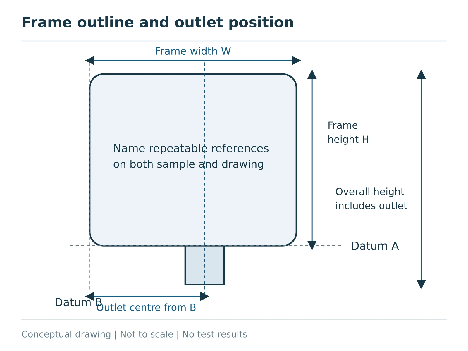
Name the main edges, centrelines or mounting faces on a front view. Two adjacent locating edges may suit a rectangular leaf. Circular or curved parts may require a centre, straight edge, outlet centreline or the original drawing datums.
Choose references that can be identified repeatedly on the sample and its mating arrangement. Do not change the starting edge without recording it.
State whether a length, width or diameter includes the outlet, lifting features, supports or projecting fittings. Record frame height separately from overall height including the outlet.
Chamfers, curved edges and irregular profiles require locating dimensions or a profile drawing. Maximum length and width cannot uniquely define them. A worn edge is not sufficient evidence for its original radius.
Locate and describe the outlet
The outlet requires more than a diameter: record its position, direction, effective engagement length and connection to the collecting manifold or seat.
| Feature | What to record | Purpose |
|---|---|---|
| Outlet location | Centreline position from named references, orientation and offset | Align with the receiving connection |
| Outlet geometry | Projection, shoulders, end features and relevant diameters | Check insertion, location and available space |
| Connection | Drawing-defined thread, flange, spigot or other interface | Establish the mating form |
| Seal location | Sealing face, groove, clamping or contact location | Establish the sealing relationship |
Thread outside diameter alone does not define a thread. Confirm its form and pitch from a drawing, marking or suitable inspection evidence. Flanges and bolted connections also require hole positions and references. If the connection is unidentified, keep detailed photographs and reliable measurements instead of assigning a similar-looking standard.
Outlet projection is not automatically effective insertion length. Shoulders, seals and the receiving part can jointly determine the installed position.
3. Separate frame thickness, seals and mounting fit
A thickness reading needs a named measurement location. A sealing requirement needs the actual mating structure.
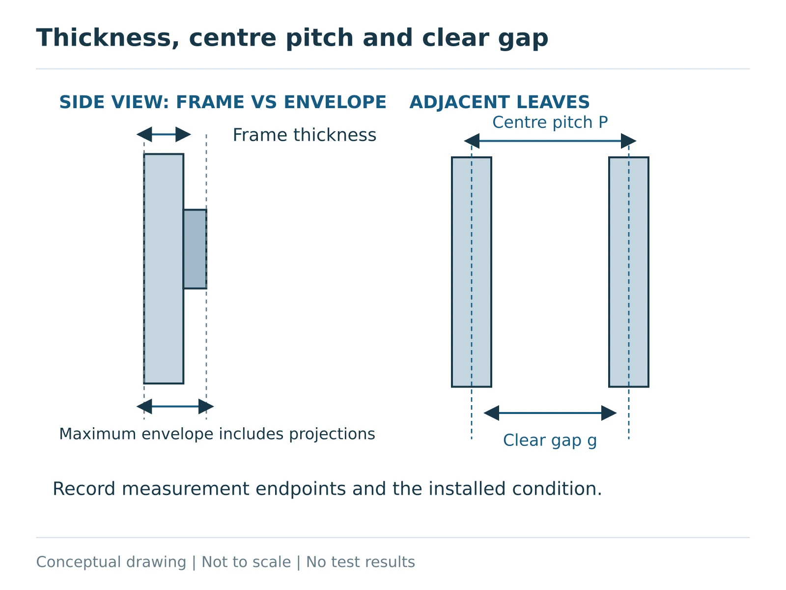
Frame cross-section thickness, maximum assembled thickness and local screen or reinforcement projections can differ. Do not record a caliper reading across a projecting feature as the frame thickness everywhere.
For guide slots, supports and locating features, record the surfaces and dimensions that actually establish fit. An overall matching outline does not confirm these local relationships.
Preserve seal and mating-part information
Where the design uses a seal ring or gasket, retain its location, cross-section or specification reference and the adjacent metal dimensions. A used seal may be compressed, worn or swollen; its present size does not establish its original specification.
Photograph and record the seal and metal mating parts separately when no drawing is available. State whether seals are included in the replacement supply. A bare-leaf measurement record does not define the whole connecting assembly.
Seal suitability also depends on material, fluid, temperature and assembly conditions. Add the relevant conditions when changing the seal material or design.
Check installation features and access
Locate lifting features, support blocks, mounting holes and clamping surfaces from the same references. Use the original drawing where available; otherwise identify which features locate and support the leaf.
Check the installation route as well as the part envelope: allow space to insert the leaf, engage the outlet and reach the fixing points.
4. Preserve filtration, support and drainage functions
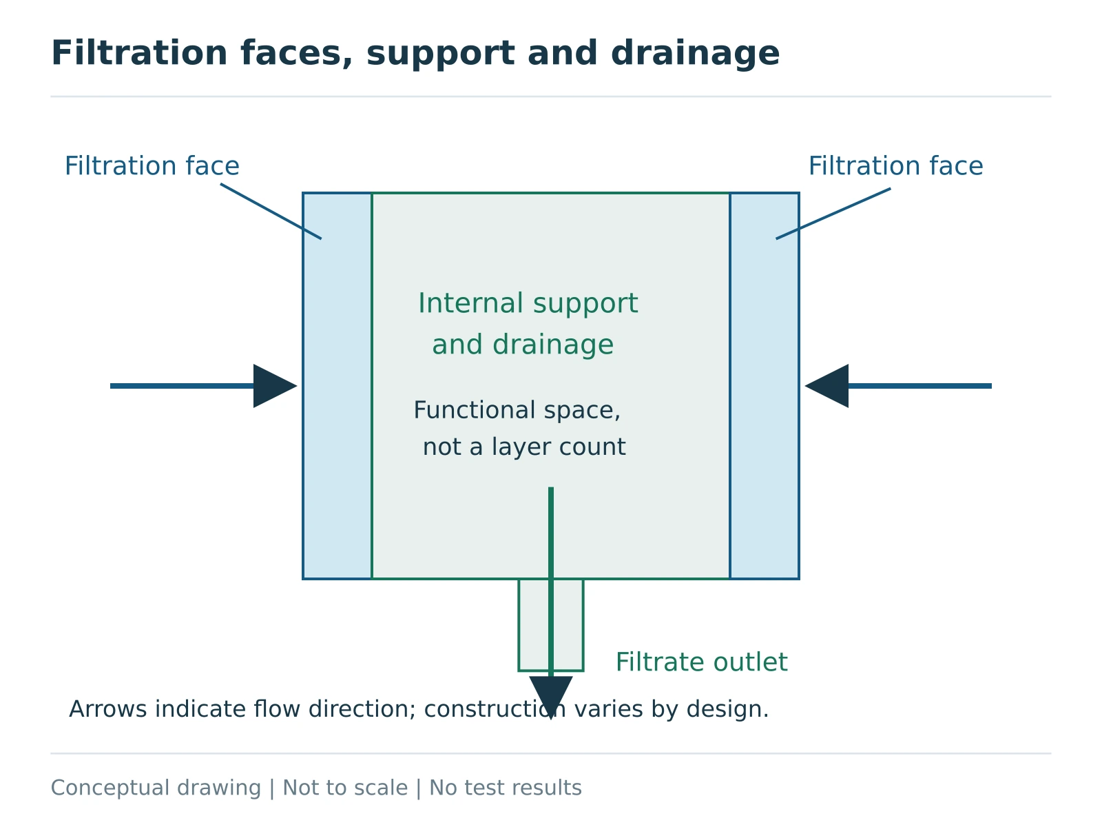
A replacement record needs both external fit and the route from the filtration faces to the outlet.
A pressure filter leaf can combine two filtration faces, internal support and drainage space feeding an outlet. US5925244A provides one public example of these functions working together [1]. Its particular construction is not a universal arrangement for all filter leaves.
| Functional region | Information to retain | If evidence is incomplete |
|---|---|---|
| Two filtration faces | Whether they match; known screen designation, alloy and fixing method | Keep close-ups and original records; do not infer rating from a photograph |
| Support | Visible support form, contact and damage | Mark hidden construction unknown |
| Drainage | Known drainage arrangement and its connection to the outlet | Consult the original section drawing; separate observation from inference |
| Frame and joints | Screen attachment near edges and outlet | Retain visible seams, fasteners and connection details |
The five-layer arrangement on our product page is a reference for one product construction. It should not automatically be applied to an unidentified used leaf. Filtration, support and drainage layers perform different jobs; five layers does not mean five identical filtration layers.
Keep an approved medium designation and its source. A photograph, mesh count or single aperture value cannot establish complete-element particle removal. Define media and complete-element requirements separately where needed; see our filter micron rating and efficiency guide.
If the task is to restore the existing design, check that design first. If you also want different flow, retention or cleaning behaviour, record those changes separately with the relevant conditions and validation requirements. Fit alone does not validate a performance change.
5. Record quantity, spacing and distortion
Relate each leaf record to the installed arrangement and list damage separately.
Distinguish quantity per variant from installation position. Use position identifiers or an equipment layout where necessary rather than only a total leaf count.
Distinguish centre pitch and clear gap
Leaf centre pitch, face-to-face clearance and equipment support spacing describe different relationships. State the measurement endpoints and whether the equipment is assembled.
Thickness, projections, supports and space occupied during operation may affect fit. Total quantity or outline area does not establish whether additional leaves can be installed. A universal minimum spacing cannot be assigned without equipment information.
Preserve the condition of a distorted sample
Photograph bowing, bending, wear and local stretching before making changes. Record measurements at several locations and the way the sample was supported.
Keep the individual readings and their locations, then compare them with a confirmed design reference. This preserves evidence of distortion that an average would hide.
An undamaged corresponding leaf can help, provided its variant and equipment position match. Original equipment drawings, part drawings or confirmed retained samples can also distinguish design features from service changes.
Alloy, hidden construction, original tolerances and allowable differential pressure cannot be fully recovered from appearance. Keep these unknowns visible until suitable evidence is available.
6. Build a replacement record from the information available
Different starting points can lead to the same reviewable part requirements.
| Starting information | Reuse directly | Fill the relevant gaps |
|---|---|---|
| Complete approved drawing | Revision, dimensions, references, medium and acceptance requirements | Quantity, changes and equipment applicability |
| Partial or equipment drawing | Defined interface, location and assembly relationships | Individual-leaf construction, missing dimensions and delivery requirements |
| Used part or sample only | Visible construction, reliable dimensions and present damage | Original requirements, hidden structure and mating evidence |
Use the short record below. Where a drawing already defines an item, enter its reference instead of copying every dimension.
| Record item | Information to enter |
|---|---|
| Identity | Sample ID; drawing/revision; equipment position |
| Outline and references | Profile; references; included projections |
| Thickness | Frame section; maximum envelope; measurement photographs |
| Outlet | Position; direction; connection evidence; related dimensions |
| Seals and installation | Mating faces; seal reference; supports and location |
| Media and internal construction | Known specification; evidence source; unknown items |
| Quantity and arrangement | Quantity per variant; positions; spacing definition |
| Condition and target | Present damage; confirmed restoration or change requirements |
| Verification and supply | Drawing requirements; supply scope; open items |
Separate trial fit from functional verification
Use trial fitting to check outline, connection position, location, spacing and access. Verify sealing under operating conditions, media integrity and filtration performance separately against the applicable project requirements.
Geometry, sealing or integrity checks and any functional tests should each follow the approved drawing or project requirements. For flow or retention verification, record the test fluid, fixture, temperature, differential pressure and acceptance target so that unlike results are not compared as equivalents.
Vessel pressure and differential pressure across the leaf are different quantities. Do not assign leaf differential-pressure capacity from the vessel rating or invent a pressure-test procedure.
You can start with your existing drawing or photographs of both faces, the side and the outlet, together with what should remain and what should change. See our pressure filter leaf product page for supply forms. Contact Our Engineers to review the remaining manufacturing and inspection details.
7. Frequently asked questions
Are outline dimensions and outlet diameter enough?
They start the discussion, but usually omit outlet location, engagement length, seals, mounting and filtration or drainage requirements. Fill the gaps relevant to this part without recreating unrelated system information.
Should a bent leaf be flattened before measurement?
Record its condition and support arrangement first. If it is remeasured after straightening or clamping, record the method and compare it with the confirmed target drawing. The altered reading does not automatically establish the original dimension.
Can the screen specification change if the outline and outlet match?
Matching fit does not establish medium suitability. A change may affect support, resistance, retention and cleaning behaviour. Preserve the original structure and define the change and its verification.
Does an equipment model remove the need for a sample or drawing?
It helps locate records, but the exact position, revision and modification history still matter. A model name or similar appearance alone does not establish full compatibility.
Is replacing a whole leaf the same as rescreening an old frame?
Whole-leaf replacement defines a new part. Rescreening also requires an assessment of the used frame, outlet, joints and cleaning condition and a separate inspection scope. New-part manufacturing capability does not establish that every used leaf is suitable for repair.
References
[1] Sheldon G. O'Rourke, US5925244A, *Beverage-screening filter leaf having woven screen supported against deflection*, 1999. Public patent text. Used only as one example of filtration, support and drainage functions; no performance, dimensional or compatibility claim is adopted.
Jack Sun works with metal mesh weaving and industrial filter manufacturing in Anping, Hebei. This article addresses replacement records and manufacturing communication; equipment procedures and project acceptance requirements remain specific to the equipment and approved design.