By Jack Sun · Filtalloy
Dry and wet operating pressure-drop readings become useful comparisons when the pressure tap span, actual gas flow, gas condition and mesh assembly are aligned. For wet operation, also retain the liquid loading and drainage condition. A higher plant reading needs those conditions before its cause can be assessed.
Dry pressure drop generally describes the resistance to gas flow without an entrained droplet load. Here, wet operating pressure drop means the total pressure drop measured while droplets are being captured and liquid is draining. Some reports use “wet pressure drop” for the additional contribution associated with liquid. Check the definition used in each report. [1][2]
Contents
- What the three measurement states describe
- Aligning two readings
- Following a change in pressure drop
- A comparison record
- Frequently asked questions
What the three measurement states describe
Start with the condition of the pad when the reading was taken.
| State | Conditions represented | Use |
|---|---|---|
| Dry test without entrained droplets | Gas flow through the specified pad and test boundary. Record cleanliness, dryness and included supports. | A baseline for that assembly and gas condition, or comparison with equivalent dry tests. |
| Stable wet operation | Gas flow with droplet capture, liquid holdup and drainage. | Compare with similar stable operation and retain the liquid-loading record. |
| Start-up or changing load | An instantaneous or averaged reading while flow or liquid distribution may be changing. | Keep the time trend and mark the operating event. Establish a baseline after the applicable stable conditions are reached. |
Dry studies help explain the effects of gas velocity and mesh structure. Wet investigations also include liquid retention and drainage. Check the apparatus, mesh and fluids before applying a published correlation. [1][2]
If a test sheet only says “pressure drop,” ask for the medium, flow, pad condition and tap locations. A pad with deposits or permanent deformation needs those conditions recorded even when a later test has no droplet loading. After cleaning, retain the cleaning, drying and dimensional-check records.
Aligning two readings
Existing drawings, test sheets and operating logs are a practical starting point. Mark any missing conditions explicitly.
Which components are between the taps?
Differential pressure is the pressure difference between two measurement locations. Taps close to the mesh and taps across a longer assembly may include different supports or local restrictions.
For example, a factory test may cover the mesh pad while a plant reading also spans a support grid and an outlet feature. Mark the taps on the equipment drawing and identify every component between them. Check instrument units, range, zero and pressure-sensing paths using the equipment procedure, especially for small, unstable or abruptly changing readings.
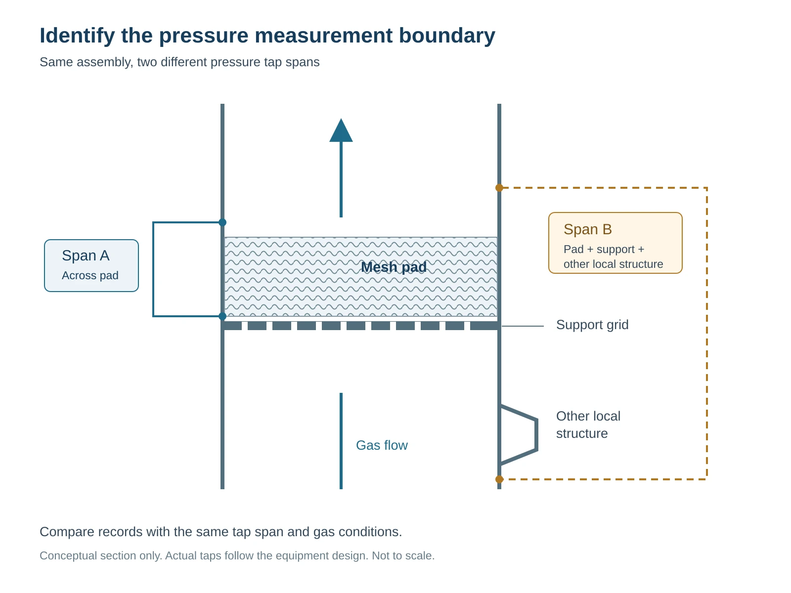
Figure 1. Span A is close to the pad. Span B includes the pad, support and another local structure. Conceptual section only. Actual tap placement follows the equipment design.
Are the gas conditions comparable?
Keep actual volume flow and effective frontal area together. If flow is reported at standard conditions, retain the reference temperature and absolute pressure as well as actual conditions at the pad.
Superficial gas velocity can organize the comparison.
u = Q / A
Here, u is superficial velocity in m/s, Q is actual volume flow at the pad in m³/s, and A is the effective frontal area corresponding to that velocity definition in m². Divide a flow in m³/h by 3600 before using it in this equation.
This relation gives an overall average. Explain how supports and obstructions are treated in the area definition. Local flow distribution depends on the equipment geometry. Changes in gas composition, temperature or pressure also call for checking gas density, viscosity and the applicability of the comparison method.
Is the assembly the same?
Check the product identity and drawing revision, then pad thickness, wire size, construction, packing density and installed condition. Equal outside diameters can conceal different mesh structures or compression.
For a replacement, compare segment arrangement, grids, fixings and perimeter fit using drawings and photographs. An existing drawing can start a manufacturing discussion. A pressure-drop or separation target also needs the corresponding operating conditions and verification requirements.
Is liquid loading defined?
Record the liquid source, changes in load and drainage observations. Where available, include liquid quantity and units, properties and temperature.
A liquid-loading figure may describe feed to an upstream vessel or droplets actually reaching the mesh. State which quantity is being used. Liquid properties, gas and liquid load, and drainage conditions influence wet behavior. One dry reading cannot uniquely determine wet operating pressure drop. [2]
Following a change in pressure drop
Locate the time of the change and compare pressure drop with gas flow, liquid loading, drainage and downstream carryover over the same interval. The following record sequence helps identify the next evidence to collect.
| Observation | Records to compare | Next check |
|---|---|---|
| Gas flow and pressure drop rise together | Actual flow, temperature, pressure, upstream load and entrainment | Compare equivalent flow conditions and confirm the equipment operating range. |
| Pressure drop gradually rises at approximately constant gas flow | Entrained liquid, drainage, deposits, instrument and sensing-path condition | Verify measurement reliability and drainage, then inspect deposits or deformation under the approved procedure. |
| Pressure drop fluctuates with changing load and carryover increases | Timing of gas/liquid changes, pressure variation, level and drainage | Keep the trend. Investigate distribution, restricted drainage, re-entrainment and installation condition. |
| Pressure drop falls while carryover persists or increases | Reduced gas flow, measurement faults, gaps or displaced mesh | Check operating conditions and measurement, then bypass and structure. Record separation performance separately. |
After cleaning, compare pressure drop under comparable conditions and continue observing drainage and downstream carryover. Assess corrosion, broken wires, collapsed mesh, damaged grids or failed fixing against the equipment and component requirements.
The existing demister pad selection guide covers velocity, density, materials, supports and general symptoms. Use the records here to connect a particular reading to those checks.
A comparison record
Write “unknown” when a condition is unavailable so the remaining uncertainty stays visible.
| Record | Dry test or baseline | Wet operation |
|---|---|---|
| Date, equipment and product ID | To record | To record |
| Tap locations and included components | To record | To record |
| Instrument, units and averaging period | To record | To record |
| Pressure drop | To record | To record |
| Gas composition, temperature, absolute pressure | To record | To record |
| Actual or referenced flow and reference conditions | To record | To record |
| Effective frontal area and superficial velocity | To record | To record |
| Pad, grids, thickness and installation | To record | To record |
| Liquid load, properties and reporting basis | No entrained droplets; note other conditions | To record |
| Drainage and downstream carryover | As applicable | To record |
| Current interpretation and missing conditions | To record | To record |
Example with missing comparison conditions
The following values are hypothetical and illustrate how to read records.
A factory sheet reports 80 Pa at an air flow of 1000 m³/h. Its volume reference and pressure tap span are missing. A plant log reports a wet total pressure drop of 150 Pa at a listed flow of 1000 m³/h. The plant span includes the mesh and support.
Subtracting gives 70 Pa. This is an arithmetic difference between the records. The missing flow reference and unmatched measurement boundary prevent assigning it to entrained liquid.
First recover the test conditions and check the plant flow basis, actual temperature and pressure. If measurement boundaries can be aligned, obtain a suitable dry baseline and stable wet record at comparable conditions. Their difference can describe additional pressure loss under those conditions. A change of load, liquid or mesh structure requires its applicability to be checked again.
Frequently asked questions
How can a plant establish a wet baseline if only a factory dry test is available?
Keep the factory test conditions. Within the approved operating range, record a period with stable gas and liquid load, normal drainage and acceptable downstream performance. Identify the mesh and installation. Use comparable later periods for trend checks. Whether a plant dry baseline can be obtained depends on the equipment and operating procedure.
Can dry pressure drop be ignored because one paper found it very small?
Check the paper’s gas velocity, mesh and measurement conditions. Small dry losses under some low-velocity tests do not establish the same result for other structures, velocities or boundaries. Retain the applicable conditions when using literature data. [1][2]
Why check carryover when pressure drop is low?
Pressure drop records flow resistance. Carryover records separation behavior. Check reduced flow, perimeter bypass and displaced mesh along with the actual duty and separation requirement.
A completed comparison should identify which readings are comparable, the conditions associated with their difference and the next evidence required. Existing drawings can confirm pad geometry, segments and supports. Add the operating conditions and acceptance requirements when discussing operating pressure drop or separation performance. Demister pads and manufacture to drawing
Jack Sun works in wire mesh weaving and industrial filter element manufacturing. Filtalloy is based in Anping, Hengshui, Hebei, China. The record format is an engineering communication aid.
References
[1] A Unified Approach for the Prediction of Dry Pressure Drop in Knitted-Wire Mesh Demisters, 2024. Original paper.
[2] Al-Dughaither, Ibrahim and Al-Masry. Investigating pressure drop across wire mesh mist eliminators in bubble column. Online 2010, volume 2011. Original paper.