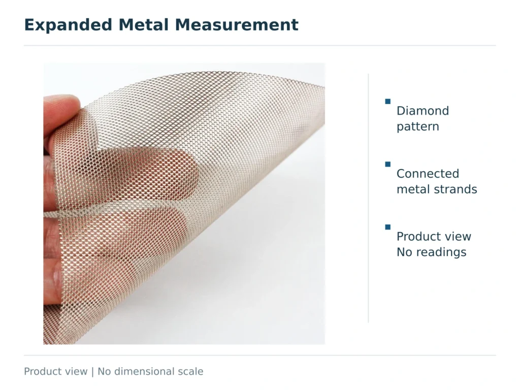
Measure expanded metal by recording the sample condition, diamond direction, pitch and clear openings, strand dimensions, and sheet edges. Keep each reading tied to a defined location. In particular, distinguish pitch from clear opening, local strand thickness from overall height, and diamond direction from the length and width of the sheet.
A useful record includes dimensions, units, measurement photographs, and whether the sample is raised or flattened. A description such as “opening × thickness × sheet size” may leave too much uncertainty for another person to repeat the measurements.
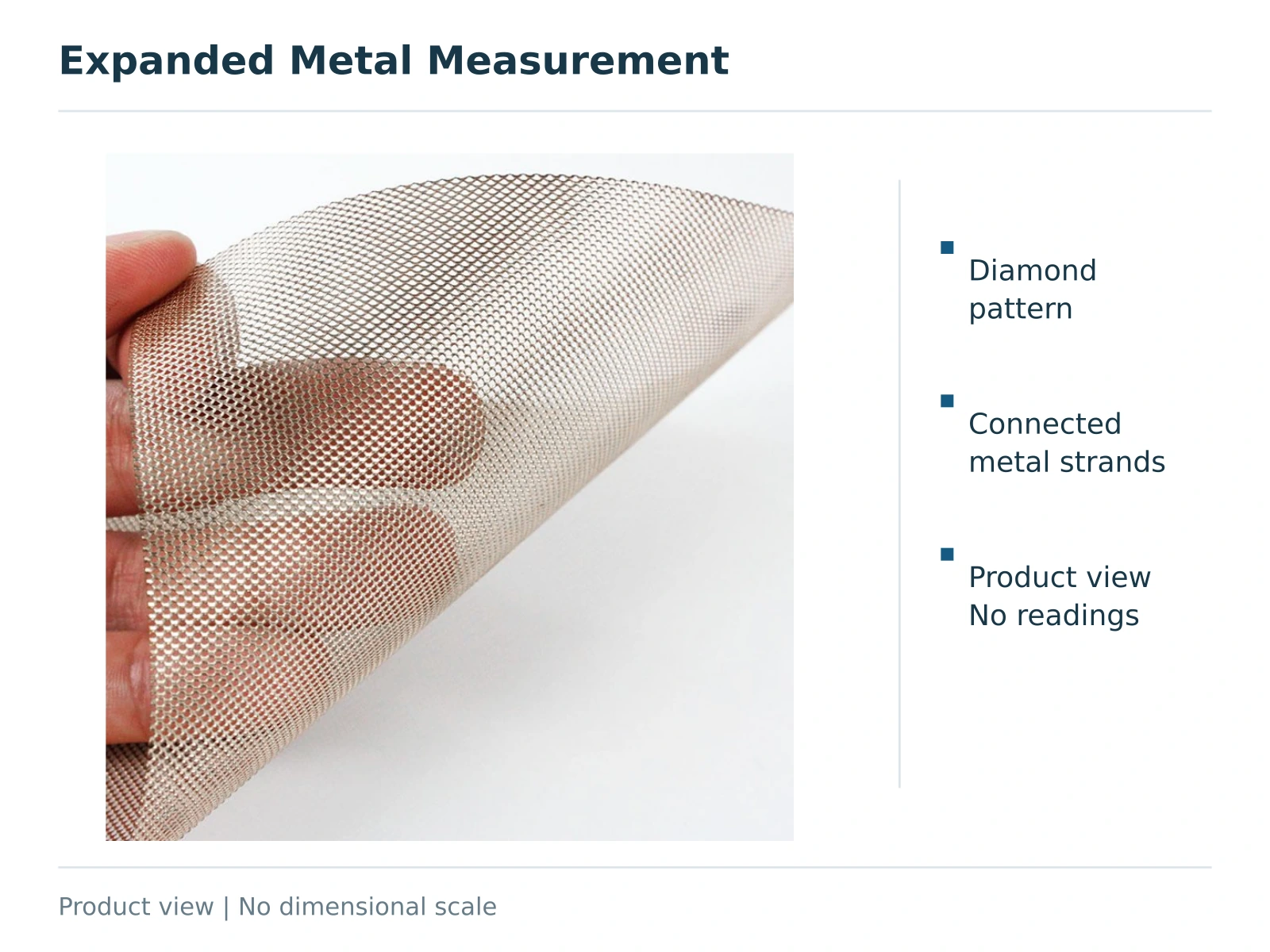
1. Sample Condition and Preparation
Record the sample as received before assigning it to a specification. Raised expanded metal retains a three-dimensional strand arrangement. Flattened expanded metal has undergone a subsequent flattening operation. These terms describe condition, not material grade or dimensional accuracy.
Take an overall photograph and record the following information.
| Item | Record | Why it matters |
|---|---|---|
| Structural condition | Raised, flattened or unconfirmed | Establishes the meaning of thickness and height |
| Surface condition | Bare, plated, coated or unknown | Finished dimensions may include the surface layer |
| Sample form | Whole sheet, cut sample, formed part or used component | A cut or damaged sample may not represent the original sheet |
| Visible damage | Bending, dents, burrs or deposits | Can affect contact and repeatability |
Write “unknown” when material grade or original sheet thickness is unsupported. Colour and magnetic response do not replace material records or compositional testing.
Use a tape or rule for overall dimensions and larger pitches. Use callipers where their measuring faces can contact the intended feature correctly. Small openings or narrow strands may require suitable optical measurement rather than forcing a calliper into the opening.
Check the instrument zero, range and contact surfaces. Display resolution alone does not establish measurement accuracy. Place the sample naturally on a flat support and note distortion before selecting measuring points. Do not compress raised mesh or pull a diamond into shape to obtain an expected reading. Record any clamping or flattening condition used during measurement.
2. Diamond Direction and Sheet References
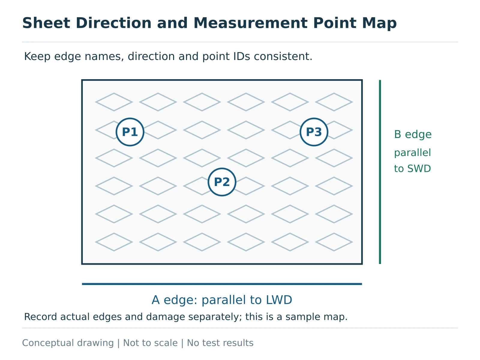
Diamond direction and sheet length or width are separate references. This guide addresses regular diamond patterns. Mark the long and short diamond directions on a front-view photograph, then name two adjacent sheet edges A and B. Keep those labels throughout the record.
| Term | Common abbreviation | Object described |
|---|---|---|
| Short-way pitch | SWD, Short Way of Diamond or Design | Pattern repeat in the short direction |
| Long-way pitch | LWD, Long Way of Diamond or Design | Pattern repeat in the long direction |
| Short-way clear opening | SWO, Short Way of Opening | Clear opening in the short direction |
| Long-way clear opening | LWO, Long Way of Opening | Clear opening in the long direction |
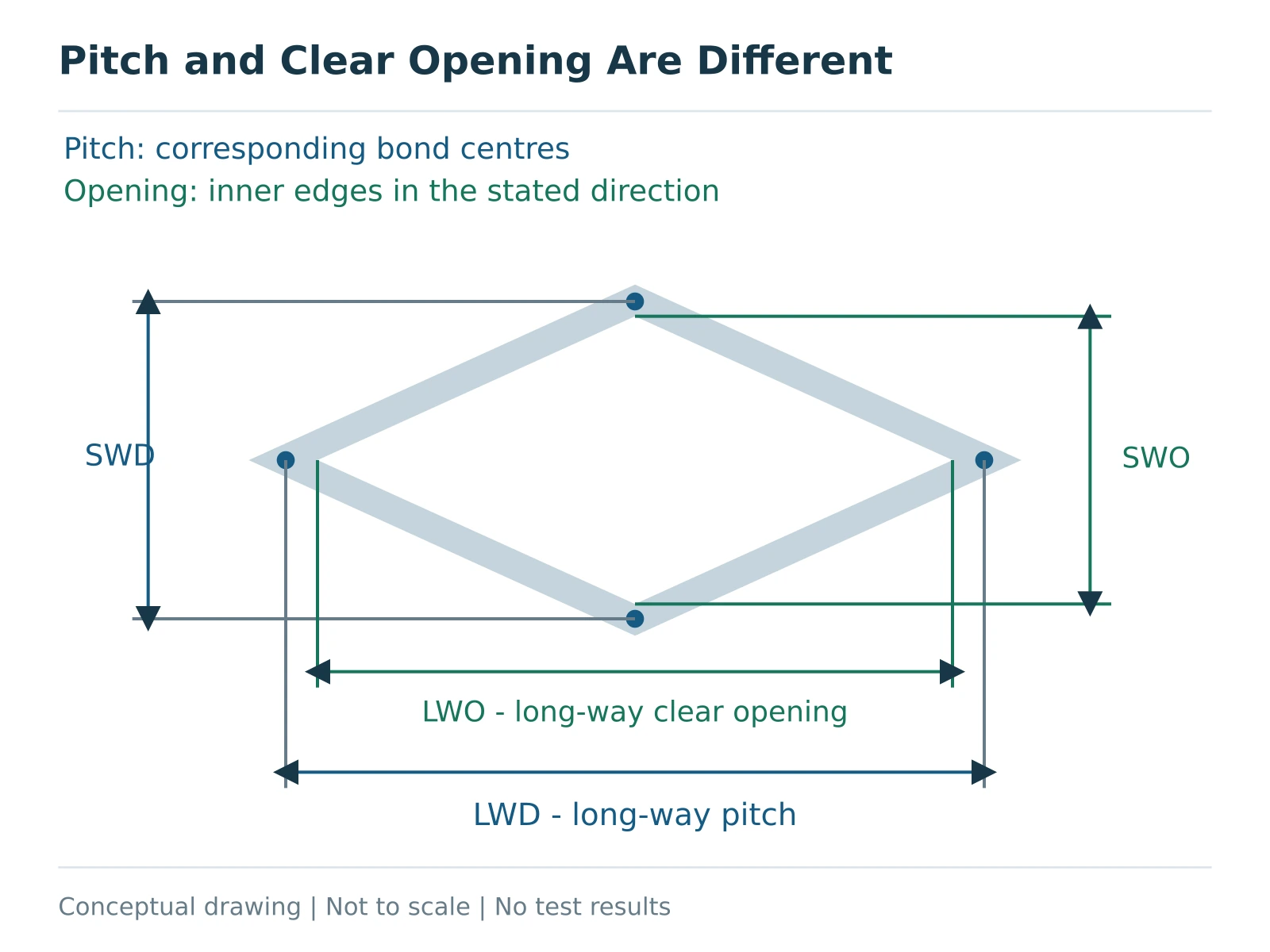
NAAMM's public technical explanation describes SWD and LWD using corresponding bond positions and treats strand dimensions separately [1]. Terminology can vary between drawings, so include endpoint arrows beside the abbreviations.
For example, record “A edge: ___ mm, parallel to LWD; B edge: ___ mm, parallel to SWD.” If the pattern runs at an angle to the edges, show that angle or provide a direction sketch. Non-diamond, asymmetric or formed patterns need references defined for their actual geometry.
3. Measuring Pitch and Clear Openings
Pitch describes repetition; clear opening describes the space between inner metal edges. Record pitch as the repeat between corresponding reference points and clear opening as the unobstructed space between metal edges, in separate fields with a stated measurement direction.
Pitch
Measure between equivalent reference points, such as corresponding bond centres, across one complete repeat in the stated direction. Keep the measurement line parallel to that direction. Avoid measuring along a diagonal strand or treating a half-repeat between staggered nodes as a full pitch. Photograph both endpoints.
For a small pattern, measuring several complete intervals may improve endpoint resolution:
Average pitch = distance between corresponding reference points ÷ number of complete intervals.
Count intervals, not nodes. Retain the total distance, interval count and endpoint photograph. An average can conceal individual variation; retain local readings when the pattern is visibly uneven.
Clear openings
Measure between the inner edges along the defined long or short direction. Let internal calliper jaws touch lightly without spreading the strands.
Raised mesh has depth, so jaw height and approach direction can change the contact points. State whether a result is a front-view projected dimension or a mechanical reading at a defined contact location. For optical measurement, keep the camera as square to the measurement plane as practical and place a scale near that plane to reduce perspective effects.
If jaws cannot reach the feature, or a burr or coating makes the boundary uncertain, record the reason rather than supplying an unstable reading. A diamond diagonal also does not directly specify the diameter of a sphere that can pass through the opening. Particle interception requires an appropriate geometric criterion or test condition.
Keep pitch, clear-opening and nearby strand measurements within the same identified region. Do not replace opening measurement with an unchecked “pitch minus strand width” formula: pattern angle, strand inclination and dimensional definitions matter.
4. Strand Width, Local Thickness and Overall Height
These describe three different aspects of the structure.
| Dimension | Position and direction | Possible interference |
|---|---|---|
| Strand width | Across a defined straight strand section | Widened bonds or oblique projection |
| Local strand thickness | Between correctly contacting local faces | Strand inclination, burrs or coating |
| Overall height | Across the mesh envelope normal to the sheet reference plane | Sheet warpage or compression |
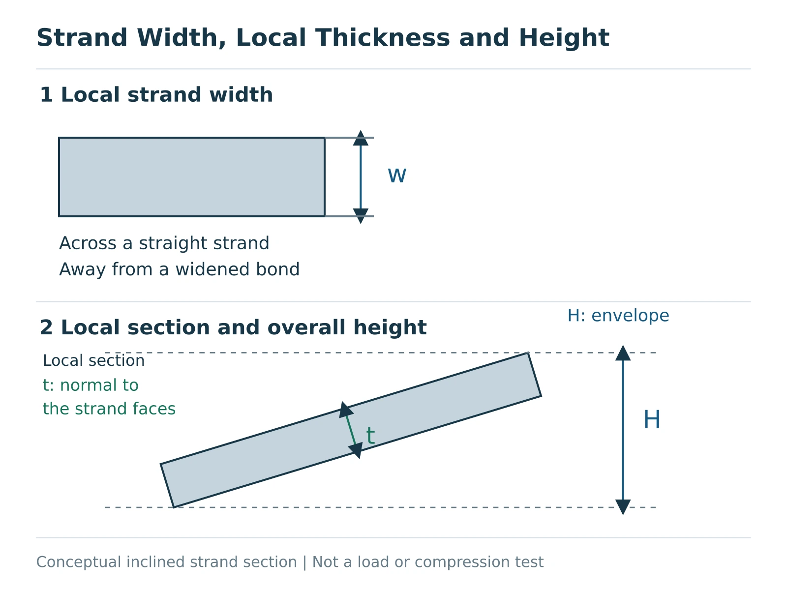
Measure width away from a widened bond or damaged region. A mechanical local-width measurement should cross the strand rather than follow an oblique line. For raised mesh, projected width in a front-view image may differ from actual local width. Identify the method and compare like with like.
For local thickness, measuring faces should contact the intended local section rather than bridge the raised structure. NAAMM also highlights contact alignment in thickness measurement [1]. Use a suitable measuring head or method if a flat calliper cannot contact a narrow or steeply inclined strand reliably. Extra clamping force is not a solution.
Original sheet thickness is relevant to raised mesh, but surface condition and measurement effects still matter. A single thickness reading on flattened mesh is insufficient to reconstruct original sheet thickness; obtain that value from material or supply records.
Overall height includes the spatial inclination of raised strands. Use suitable parallel measuring faces or a thickness arrangement without visibly compressing the sample, and record location and support conditions. Distinguish local structural height from the space occupied by whole-sheet warpage. Simply measuring from a support surface to a warped high point can include both.
Flattened material can retain local unevenness, burrs or bond relief. Do not assume local thickness and overall envelope are identical everywhere because the material is called flattened.
5. Sheet Dimensions, Edges and Measurement Locations
State the endpoints as well as the size. Record the dimensions along A and B. Where cut strands protrude, specify whether the dimension uses the outer envelope or a drawing datum. Irregular sheets benefit from an outline sketch rather than only two maximum dimensions.
Photograph all edges and corners. Record bond-cut, open or mixed edge conditions. A fixed outline and a fully closed diamond border cannot be independently assumed: cutting positions relate to the pattern repeat. Confirm any closed-edge requirement against the actual pattern, direction and dimensions.
For an initial sample record, select representative regions near the middle and both sides. Use undamaged areas to describe the regular structure and record damaged areas separately. This is a practical communication approach, not a prescribed standard sampling plan.
When comparing batches, retain consistent instruments, direction, contact and point-selection rules. Keep raw readings; one average cannot explain local differences. For acceptance, compare results against agreed drawing values, tolerances, sampling and decision rules. NAAMM's official catalogue lists EMMA 557-25 with terminology and manufacturing tolerances [2]; this guide does not reproduce its acceptance procedure.
6. Sample Measurement Record
Use consistent units. Retain “unknown” rather than inferring unavailable information from appearance.
| Item | Entry |
|---|---|
| Sample ID, date and recorder | ___ |
| Condition | Raised / flattened / unconfirmed |
| Material and evidence | ___; certificate / drawing / unknown |
| Surface state | ___; dimensions include surface layer: yes / no / unknown |
| A/B edges and pattern direction | ___; photograph ID ___ |
| Damage and edge state | ___ |
| Instrument, method and support | ___ |
| Measurement | Reading; units ___ | Location or method |
|---|---|---|
| SWD pitch | ___ | Endpoint photo ___; ___ complete intervals |
| LWD pitch | ___ | Endpoint photo ___; ___ complete intervals |
| SWO clear opening | ___ | Inner edges; contact or projection ___ |
| LWO clear opening | ___ | Inner edges; contact or projection ___ |
| Strand width | ___ | Straight section; actual or projected ___ |
| Local strand thickness | ___ | Point, contact head and surface ___ |
| Overall height | ___ | Support, contact and warpage ___ |
| A/B sheet dimensions | ___ | Envelope or drawing reference ___ |
| Original sheet thickness | ___ / unknown | Material or supply record ___ |
Number individual locations. Do not assemble minima and maxima from unrelated points into one apparent sample. If only three photographs are available, prioritise an overall front view, a side view showing relief, and a measurement view showing both contact points and the reading.
Start with the drawing you have. With incomplete information, separate confirmed dimensions from unknowns. Visit our expanded metal page to discuss sample dimensions or manufacturing requirements with our engineers.
7. Frequently Asked Questions
Why do two people obtain different readings on the same sample?
Compare endpoints, direction, sample condition and contact first. Pitch and opening, or local thickness and overall height, are different objects. Side-by-side measurement photographs can reveal the mismatch.
Can I squeeze raised mesh flat with a calliper to measure thickness?
That produces a result under compression and may alter the sample. Measure natural height or local thickness without visibly changing the structure. If a compressed dimension is required, agree the load and conditions separately.
Do I still need clear-opening dimensions when pitch and width are known?
Retain them when actual opening is relevant. Pitch alone does not define the opening. Only use a geometric conversion after checking that the model and definitions match.
Can a used sample fully recover the original specification?
Undamaged regions provide clues, but wear, corrosion, flattening, coating and cutting may change or remove information. Keep repeatable observations separate from unknown original values.
Do dimensions establish strength or filtration rating?
They describe geometry, not complete performance. Strength also involves material, orientation, support, joints and loading; filtration involves opening geometry, particles and test conditions. Use the applicable design basis or test evidence.
References
- NAAMM/EMMA, *Expanded Standard: What You Need to Know*. Public explanation used for dimensional references and measurement contact; older standard identifiers in that article are not treated as current acceptance editions. https://naamm.org/news/expanded-standard-what-you-need-to-know/
- NAAMM/EMMA, *Standards for Expanded Metal*, EMMA 557-25, 2025. The official catalogue's edition and scope were checked; its full PDF was not available for this review, so no detailed tolerance or sampling clauses are reproduced. https://naamm.org/publications/standards-for-expanded-metal/
The record method and illustrations are communication aids, not test reports or a standard acceptance procedure.