By Jack Sun · Updated October 22, 2026
The sintered wire mesh manufacturing process starts with individual woven meshes. Cleaning, layup, locating and sintering establish bonds at contact points. Cutting, forming or joining then follow according to the delivery form. The aim is a laminate bonded as designed, retaining the required flow passages and suitable for its subsequent processing or use.
Locating the meshes, bonding them in a furnace and joining a cartridge happen at different stages. Their relationship explains why forming an acceptable sheet into a cylinder and adding end fittings introduces further dimensional and integrity checks.
From woven mesh to a sintered sheet
Interwoven wires provide the original openings and geometry. Sintering establishes metallurgical bonds at suitable contact points, creating a laminate through which fluid can still pass along interconnected pores. [1]
This differs from melting metal and casting a solid plate. A filter medium needs control of both interlayer bonding and pore structure. Producing something that looks like a single sheet does not fulfill the entire process requirement.
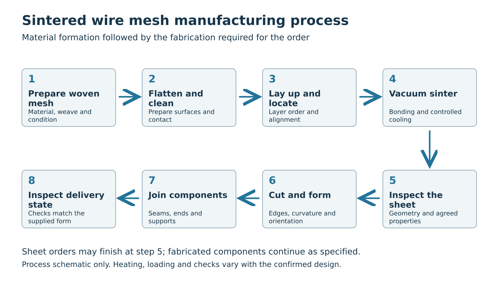
In one of our standard five-layer routes, individual meshes are flattened and cleaned before layup and spot locating. The stack is then loaded for vacuum sintering and controlled cooling. Other materials or constructions need a suitable process of their own; the name “five-layer mesh” does not specify one universal set of parameters.
Preparing, flattening and cleaning the meshes
Before sintering, each mesh already has its material, weave, wire diameter and opening geometry. Layup and bonding depend on these inputs, so preparation begins by confirming the mesh actually used for each layer.
A filtration mesh and a support mesh may both be stainless steel while serving different functions. Changes in weave or wire diameter can change contact locations, layer thickness and flow space. Preparation therefore follows the layer specification, rather than treating meshes of the same outline as identical materials.
Flattening changes contact geometry
Woven mesh has crimp where warp and weft interlace. In our standard route, flattening the individual layers before sintering helps control their subsequent contact and thickness during layup.
This operation acts on mesh geometry; it is not a pass through equipment that leaves every specification entirely unchanged. Surface condition, thickness and mesh state after flattening still need to match the layer’s requirements. Flattening an individual mesh before layup also differs from leveling an already sintered sheet.
Cleaning prepares surfaces for contact and bonding
Oil and other residues change the condition of the surfaces that must subsequently contact and bond. Cleaning involves removal of contamination, control of remaining residues and protection of the mesh itself. Handling and storage between cleaning and layup also belong to this stage.
This is preparation before sintering. Cleaning an element after service involves different contaminants, structures and reuse decisions; the same treatment cannot automatically be applied to both tasks.
Layup and spot locating
Layup turns a list of mesh specifications into a defined spatial arrangement. It establishes the filtration-layer position, the specified inlet face and the transition between supports.
Our standard five-layer arrangement provides protection, filtration, distribution and two support layers. Layup preserves the specified order and coverage while preventing creases, inclusions or local damage from entering the stack. See sintered wire mesh structure, layers and flow for the individual functions.
In this factory route, four-corner spot welds locate the assembled meshes during handling and loading. These spots provide positioning; they do not establish the required sintered bond across the whole sheet.
A sound-looking locating point describes that local connection. Evaluating the laminate still requires the subsequent sintering and inspection results. Likewise, one locating-weld arrangement does not define every requirement for finished cartridge joints.
Bonding and loading during vacuum sintering
The loaded stack undergoes a controlled thermal process. Temperature, environment, holding time and loading work together with the material and layup to establish the required bonds while controlling pore geometry and shape. Primary technical literature relates this bonding to atomic diffusion at contact interfaces. [1][2]
Loading and the position of separators
In our established loading route, suitable separating layers are placed between separate laminate blanks to prevent them bonding to one another. These separators belong between different blanks, rather than between the functional mesh layers that are intended to bond.
Platens used with the loading arrangement help maintain contact and sheet condition. Their role depends on the furnace loading method. A platen on top of a stack does not, by itself, demonstrate the use of hydraulic hot-press equipment.
Conventional vacuum and hot-press routes
Our process references include conventional vacuum sintering and vacuum hot pressing. The conventional route uses platens with the loading arrangement; hot pressing applies a controlled external load during the thermal process. These are different loading methods, rather than evidence that every sintered mesh must undergo high-pressure pressing.
| Process consideration | What it affects | Distinction to preserve |
|---|---|---|
| Furnace environment and thermal program | Surface condition, bonding and material changes | A vacuum environment is not a bond-quality report |
| Contact and loading | Mesh contact, geometry and bond development | Manufacturing load is not allowable service differential pressure |
| Cooling and unloading | Material and geometry after thermal processing | Leaving the furnace does not complete every delivery inspection |
Higher temperature, longer holding or greater load cannot simply be described as better bonding. The process must also meet requirements for pores, thickness, flatness and downstream fabrication. Together, these requirements determine a suitable program for a particular mesh combination.
Manufacturing load and a filter’s operating differential pressure belong to different stages. Even where external pressure is applied during processing, its value cannot be copied into a working-pressure rating for the medium or finished element.
Controlled cooling and subsequent inspection
After the thermal process, cooling follows the applicable procedure before unloading and inspection. Flatness, thickness and visible abnormalities need assessment in that state.
If delivery includes leveling or other finishing, the relevant dimensions need checking in the final state. A thickness or flatness record taken before finishing may omit changes introduced afterward.
Inspecting the sintered sheet
Inspection now concerns a bonded laminate rather than separate starting meshes. Appearance and geometry reveal some issues; different performance requirements still need different evidence.
Visible layer lines at a sheet edge do not necessarily indicate delamination. Different meshes remain part of the structure. Assessing abnormal gaps, lifted regions or bonding problems requires the specified observation locations and methods. A flat surface alone likewise cannot establish bond condition at every internal location.
Dimensions, thickness, flatness and edges are basic sheet checks. Interlayer bonding, pore structure, flow properties and particle retention are evaluated using the methods specified for the order. One photograph or thickness measurement cannot establish them all.
Flow data are more useful when the measurement boundaries align. Fluid, temperature, effective area and differential pressure belong with the result. See sintered mesh differential-pressure calculations for calculations and reference points.
Cutting, rolling and final joining
A sintered sheet may become a panel, disc or cylindrical medium according to the delivery requirement. Each operation brings the material into new geometric and connection relationships.
Edges after cutting
The cutting method needs to suit the laminate, thickness, outline and edge requirements. Examine cut edges for burrs, local distortion, lifted layers or filtration-layer damage affecting use. Subsequent edging, welding and installation position influence the required treatment.
Sintered bonding does not make every cutting method produce the same edge. An edge within the filtration boundary affects the complete flow path; an edge entering a joint needs consideration with that connection. The wire mesh cutting and edge-quality article explains general methods. The particular laminate still needs assessment against its sample and processing requirements.
Structure after rolling or bending
Forming a curve produces different deformation through the thickness. Original thickness, layer combination and forming direction therefore influence the outcome. Stainless steel as a material designation does not establish one bending radius for every sintered mesh.
For cylindrical parts, examine layer condition, cut edges, filtration-layer orientation and contact with supports, as well as diameter and roundness. Correct dimensions do not complete the manufacturing task if forming has damaged the filtration layer.
Longitudinal seams and end connections
A longitudinal seam closes the cylinder; end connections attach it to the installation structure. These joints have different responsibilities from the locating spots before sintering. Some carry loads, and some also form part of the filtration boundary, requiring control of bypass paths.
Choose the welding method, joint form and acceptance requirements around those responsibilities. See wire mesh filter welding joints for lap joints, butt joints and cover-strip arrangements.
Inspection for the delivered form
The same sintered medium can be supplied at different stages. A sheet record describes its result under the stated conditions. Changes added by forming or assembly need confirmation at the corresponding stage.
| Delivered form | Main or additional inspection objects | What the record covers |
|---|---|---|
| Sintered sheet | Laminate, dimensions, flatness and agreed material properties | The inspected sheet and test boundary |
| Cut or formed part | Outline, edges, curvature, layer orientation and processed condition | The part after the specified operations |
| Complete cartridge or plate | Joints, ends, seal interfaces, supports and filtration path | The finished construction and agreed validation scope |
Bubble and flow tests retain their separate meanings. The public scope of ISO 4003 identifies the bubble test as a quality-control method; it cannot directly determine filtration rating or a complete pore-size distribution. ISO 4022 addresses fluid-permeability determination for permeable sintered metal materials. [3][4] A result from one test does not automatically fulfill another task.
A material report likewise does not automatically cover seams added during rolling or installation seals. Where an order requires finished-component validation, use the specified boundary and checks rather than copying sheet test values into an element-performance statement.
We supply sintered mesh sheets and manufacture discs, panels and cylindrical components to drawings. With an existing drawing or specification, discussion can start from the required delivery form. Requirements already defined on a drawing do not need to be entered again into a full operating-condition questionnaire. See our sintered mesh media and filter elements and sintered mesh filter plates for supply forms and specifications.
Frequently asked questions
Is sintered wire mesh always made from metal powder?
The material discussed here starts with woven metal mesh. Powder-sintered media start mainly with metal powder, while fiber felt uses a metal-fiber structure. All can involve sintering, but their starting structures and manufacturing routes differ.
How does individual-mesh flattening differ from post-sintering leveling?
The first prepares starting-mesh contact and geometry before layup. The second adjusts the geometry of an already bonded sheet. The objects and stages differ; dimensional records should identify the actual delivery state.
Does one weld prove that the entire sheet is sinter-bonded?
No. A local weld corresponds to its connection position and function. Interlayer bonding across a sheet needs evaluation using the methods and records required for that material.
Can I start with only a finished-part drawing?
Yes. Start with the existing drawing, check material, layer requirements, dimensions and delivery form, and clarify gaps affecting manufacture or acceptance. Further operating conditions are needed when the task also involves assessing a new construction’s suitability or performance.
From layup to finished element, the object being examined changes: first the starting meshes, then interlayer bonds, then formed geometry and joints. Matching those objects to the delivered form turns a “sintered mesh” requirement into the sheet or component actually needed.
Technical sources
GKD — Sintered Mesh. Public glossary; accessed October 22, 2026.
Nichidai — Sintered Wire Mesh. General principles of diffusion bonding at contact interfaces; manufacturer-specific cleaning or life guarantees are not adopted here.
ISO 4003:1977 — Determination of bubble test pore size. Public scope.
ISO 4022:2018 — Determination of fluid permeability. Public scope.
About the author: Jack Sun has long worked in metal wire mesh weaving and industrial filter-element manufacturing. Filtalloy is based in Anping, Hengshui, Hebei, China, known for wire mesh manufacturing.