By Jack Sun · Filtalloy, Anping, Hebei, China · October 19, 2026
When reviewing a rolled mesh filter cylinder, the seam often attracts the first questions: which welding method should be used, can the joint be stronger, and could particles pass through it? These questions require different kinds of evidence.
Wire mesh welding requirements depend on the joint's function. Weld points fixing layers mainly address position. An end-ring connection also transfers loads. A joint on the filtration boundary needs control of paths around the filtering mesh. Define these duties before selecting a method, structure and acceptance checks.
This article concerns filter cylinders, discs and related components fabricated from woven metal mesh. Its purpose is to turn service needs into joint requirements for design, manufacturing and sample confirmation.
What each joint needs to do
Different connections on one cylinder may serve different functions. A few points between inner and outer layers can hold them in position. A longitudinal seam forms a cylinder. End connections secure it to mounting components. Similar processes may be used, while acceptance requirements differ.
| Main joint function | Design concern | Sample-confirmation focus |
|---|---|---|
| Fix mesh layers or assist assembly | Layer movement and effect on active filtering area | Position, stability and wire damage |
| Connect a cylinder to an end ring or support | Load transfer during installation and cleaning | Joint continuity, dimensions and agreed load validation |
| Form part of the filtration boundary | Bypass at seams, ends or between layers | Seam path, edge coverage and functional validation |
A filter intentionally allows fluid through its openings. The goal is to route it through the specified medium. A larger unintended path at a seam may pass particles even when the mesh itself has the correct specification.
Secure locating points can fulfil a fixing task. When the same connection also forms a retention boundary, review the complete path between points, along mesh edges and through end transitions. Joint strength and control of the filtration path need separate confirmation.
Relate the joining method to mesh and mating parts
Mesh count alone rarely answers whether a particular mesh can be welded as intended. Wire diameter, weave, number of layers, material and the plate or end ring all affect the sample combination. Meshes with the same count but different wire diameters or weaves can have different contact conditions.
Resistance welding applies current under controlled force to generate heat at the joint interface. AMADA WELD TECH also identifies surface roughness, cleanliness, oxidation and coatings as influences on contact resistance.[1] Using production-representative mesh and surface condition is therefore more informative than specifying only a welding current.
Joining fine mesh to a thicker ring also requires stable local fit: edge contact, movement under clamping and repeatable contact in the joining region. Insufficient energy may leave an incomplete connection; unsuitable input may damage wires. Establish the process window using samples of the actual combination.
Laser welding uses a focused beam to apply localized heat and is another method that can be evaluated for fine joining.[2] Suitability depends on joint shape, assembly gaps, materials and sample results. Naming the method alone does not define load capacity or filtration-path integrity, nor does this discussion establish that a particular process is available for every Filtalloy component.
Keep three descriptions distinct. The process describes how the connection forms, such as resistance or laser welding. The joint geometry describes how parts fit, such as a lap, butt or cover-strip arrangement. The weld layout describes where connections are placed, such as discrete points or a defined connected path. This helps distinguish a specified method from the function that needs to be achieved.
Lap joints, butt joints and cover strips
A lap joint overlaps mesh edges to form a joining region, while increasing local thickness. In an insert-type cylinder, that increase can affect installation clearance. Where fine mesh contacts a support cylinder, examine whether a raised seam creates local contact or wear.
A butt arrangement brings edges together at the seam and reduces mesh overlap, but imposes different requirements on cutting, alignment and clamping. Mesh has openings and discrete wires at its edge, so a joint cannot simply copy a solid-sheet design of similar thickness.
A cover strip or edge enclosure adds a joining and protection region. TWI's joining literature discusses resistance joining between mesh and plate, including an arrangement that sandwiches mesh beneath a cover plate.[3] It provides a design concept; a project still needs the strip material, width, fit and connection path defined.
These geometries affect local thickness, available flow area and access during cleaning. Useful design questions include: how much seam thickness does installation allow? Is the seam in an active filtering area? Where may particles collect? How will cleaning flow act on the edge?
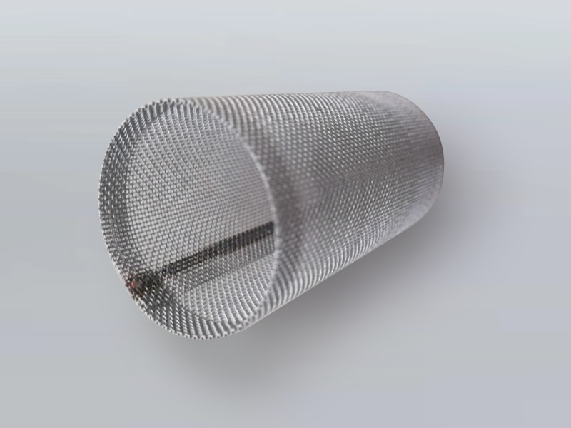
Filtalloy's custom wire mesh filter components show rolled cylinders, end connections and different edge structures. Product shapes help explain fit, while drawings and sample records establish welding requirements.
Match inspection to the service requirement
Start with visible joint condition: missed connections, burn-through, broken wires, loose edges, changes to nearby openings and finished dimensions. These observations reveal some problems and help locate further validation.
Then return to the defined function.
| Requirement to confirm | Possible agreed check | Conditions to record |
|---|---|---|
| Mesh and edge condition near the joint | Visual or magnified inspection and measurement | Regions, method, permitted defects and dimensions |
| Fixing and connection stability | Pull, peel or component loading related to service forces | Load location, fixture, direction, acceptance and sampling |
| Unintended filtration-boundary paths | An agreed particle challenge or other applicable integrity evaluation | Fluid, direction, particle conditions, decision method and test coverage |
The table organizes project requirements; it is not a universal mandatory test plan. A connection used only during assembly may need different loading from an end connection exposed to reverse cleaning.
For bypass concerns, review more than the longitudinal seam. Its intersection with an end ring, fine mesh entering an edge enclosure and edges between layers all belong to the complete flow path. If a complete-component test identifies an abnormal result, local checks can help locate the source.
Use an established confirmed procedure where one exists. For a new construction, establish both method and acceptance criteria during sampling. “Weld firmly, no leakage” leaves room for different interpretations because the filter is designed to pass fluid.
Make customization information actionable
A drawing marked only “lap joint, spot welded” describes part of the geometry and layout. It leaves open whether the points only locate the cylinder or also form a retention boundary, what seam thickness is allowed, and how the ends connect to the filtration layer.
Organize the following information in the same drawing or technical package.
Mesh and mating components. State material, openings or mesh specification, wire diameter, weave, layer order, and the materials and dimensions of rings, strips and supports. Keep joint close-ups and section information from an accepted old component where available.
Joint locations and duties. Identify longitudinal, end and interlayer connections separately. Assign positioning, loading or filtration-boundary duties, and mark permitted joining areas and active mesh that needs protection.
Service and finishing conditions. Provide flow direction, relevant normal and abnormal loads, temperature, medium and cleaning method. Include post-weld cleaning, surface treatment or cleanliness requirements in sample confirmation so the delivered condition matches intended use.
Acceptance and changes. Agree inspection locations, dimensions, functional validation and records. Define which confirmations need review after a change to mesh, layer count, end rings or joint geometry. The sample conclusion then has a clear scope.
This cylinder example illustrates how to complete manufacturing information; it is not a customer case. If only an old component or partial photographs are available, send the existing information and begin by establishing each joint's function.
Frequently asked questions
Will more weld points improve filtration?
Point count affects connection distribution. Filtration also depends on mesh and the complete seam path. More points may not resolve uncontrolled paths at an edge or end. Identify the path first, then review the layout and its effects on wires, thickness and active area.
Can the seam be exactly as thin as the mesh?
This depends on joint geometry and mesh construction. A lap adds layers and a cover strip adds solid material; a butt joint has its own edge-fit requirements. For tight installation clearance, define allowed seam thickness and measuring locations during design.
Does changing one fine layer need reconfirmation?
Assess whether it changes the connection. A new fine layer may alter thickness, contact and edge paths. Review the affected region and use the scope of earlier validation to decide which checks need repeating.
Can photographs establish joint acceptance?
Clear images describe position, shape and some visible defects. Internal connection condition, load capacity and filtration function need appropriate records or validation. Overall, seam close-up and end-transition views make remote discussion more useful.
Connect joint duties with acceptance
When joint duties, mating geometry and acceptance conditions are linked, sampling has a clear purpose: demonstrate what each connection needs to do using relevant observations and validation.
Technical references
1. AMADA WELD TECH, Resistance Welding. Used for the process principle and surface-condition effects, not equipment-performance claims.
2. AMADA WELD TECH, Fiber Laser Welding. Used for localized heat-input principles, not a claim of Filtalloy laser-equipment capability.
3. TWI, Transition Joints Between Dissimilar Materials, 2006, section 1.3, pages 5–6. Original paper. Used for mesh-to-plate joining and cover-strip concepts; its examples are not filter-sealing validation.