By Jack Sun · Filtalloy, Anping, Hebei, China · October 19, 2026
A resin trap screen in an ion-exchange system retains resin particles entering a specified flow path. Start by defining whether the target is intact beads, fragments or other particles. Then connect particle condition, flow, possible carryover, direction and installation fit to slot and structural requirements.
When resin appears downstream of an ion-exchange vessel, adding a trap or reducing the existing slot can seem like an obvious response. First establish what is actually present: whole beads or broken fines. Both may need interception, but they do not necessarily call for the same screen.
The trap and upstream resin-retaining components
The trap intercepts target particles in its designated flow path. It is related to the nozzles, collectors and distributors in a resin bed, but their locations and functions differ.
Bed-retaining components distribute or collect fluid while retaining resin. A downstream trap provides an additional physical interception point for particles that have entered the pipe. Adding one does not repair a leaking upstream component.
Use the process flow diagram to define the location: which pipe or downstream equipment needs protection? Does the path change during normal service, flushing or other operating stages? Does all relevant liquid pass through the same trap?
LANXESS's Lewatit literature includes appropriate resin trapping to avoid resin loss in a particular startup context, alongside checks of distributors, collectors and outlet screens.[1] This helps explain how the measures relate. The system design still determines the installation point and operating arrangement.
Also define the supply scope. Replacing the internal screen element is different from specifying a complete device with housing, monitoring and cleaning provisions. Confirmation of the element does not confirm every function of the complete assembly.
Whole beads and resin fragments
A representative particle diameter does not fully describe the retention target. If smaller beads or broken fragments matter, review the lower end of the distribution and the actual particle shape.
For example, DuPont's AmberLite IRC100 Na data sheet lists particle-diameter information and a separate smaller-particle proportion.[2] Its numerical values are not used here as universal slot-selection values. The point is to read the complete particle-size description rather than selecting only a central number.
Distinguish new resin, resin in service and material collected from the trap or downstream. Record sample location, operating stage and wet condition. Supplier literature identifies the original resin; field samples describe the present interception task.
Intact beads and irregular fragments can pass openings differently. A fragment may be longer than the slot but narrow enough in another direction to pass. Consider deformation under actual conditions where relevant.
DuPont's water-conditioning manual discusses osmotic shock and mechanical attrition among resin-damage mechanisms, with fragments and fines affecting operation.[3] Investigate both interception and continued fragment generation so each response addresses the appropriate problem.
A photograph is useful for describing shape. Without a scale and sampling background, it cannot directly establish a manufacturing slot width. Suitable dimensional observation or particle analysis may still be needed.
Slot width, opening area and carryover
The retention task informs the opening requirement; flow and accumulation conditions determine whether the resulting construction is usable. A smaller slot alone does not resolve design flow, particle accumulation and cleaning arrangements.
For wedge wire, define nominal clear slot width, permitted variation and working face. If local maximum openings matter, state that separately. A nominal value is not a measurement of every position. A retention percentage also needs a sample, method and acceptance conditions.
Equal slot widths can have different net opening areas because wire face width, unslotted edges and support arrangements differ. Use the wedge wire open area calculator for geometric checks and the slot specification guide for the area boundaries. Operating resistance still needs evidence for the complete component and actual fluid.
Discuss the possible resin quantity as well. Occasional minor carryover and an abnormal release impose different accumulation, resistance and response requirements. Equal pipe size does not establish equal element requirements.
Describe three operating states: a clean element passing design flow; an element with accumulated particles; and the agreed intervention condition. Before sampling, identify what is observed in each state, how it is monitored and who responds.
Where finer fragments create a separate downstream particle-control task, evaluate additional filtration with a clearly defined role. The actual particles and system conditions determine whether it is needed and which medium is appropriate. A resin trap is not automatically the final barrier for every fine particle.
Flow direction, connections and loading
An element fitting inside a housing is only part of the requirement. The fluid must also pass through the intended screening face.
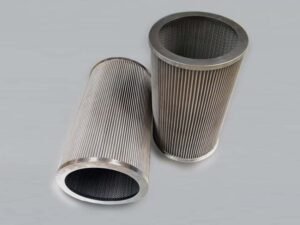
For cylindrical wedge wire, show inside-to-outside or outside-to-inside through-flow, inlet, outlet, closed end and connection end on a section. Identify reverse-flow or cleaning stages separately where they occur.
Review the path through the screen and any potential bypass at interfaces or mating clearances. Suitable slots address the screening face; end connections and sealing fit still need drawing-based confirmation.
Distinguish pipe or housing pressure from differential pressure across the element. Specify loading in the relevant directions, temperature and support. A system-pressure value cannot simply be treated as the element's allowable differential pressure.
Select materials for the actual contact liquids and operating stages. Supply regenerant and cleaning-fluid compositions and conditions as well as normal service water. Interface photographs and overall dimensions help, but do not replace this service information.
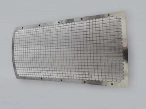
Filtalloy's wedge wire screen page shows flanged resin trap elements among other structures. The confirmed drawing and service conditions define the screening face, supports, interfaces and inspection requirements.

What collected particles can tell you
Collected material is useful evidence when interpreted with sample location and operating records. Seeing resin does not, by itself, identify which upstream part has failed.
| Observation | Evidence to add | Question it helps examine |
|---|---|---|
| More intact beads | Operating stage and upstream retaining-component condition | An unintended route into the flow path |
| Mainly fines | Particle sizes, resin history and condition analysis | Original small particles or fragments generated in service |
| Resin mixed with deposits | Composition, resistance changes and feed records | The contribution of resin and other plugging material |
| Particles after the trap | Samples before and after, actual slots and interface checks | Passage through slots, bypass or a downstream source |
DuPont's troubleshooting guidance for sudden substantial resin loss includes checking vessels and distribution systems for leaks.[3] System personnel should define the investigation from the evidence. The table provides investigation directions rather than a complete diagnosis.
When differential-pressure trends are available, record tap locations, flow and temperature. Relating collected material, resistance changes and downstream particles over the same period is more informative than an isolated observation.
After corrective work, return to the original protection task: what remains downstream, how has collected material changed, and is resistance acceptable under comparable conditions? Replacing an element and verifying the protection task are separate milestones.
From existing information to sample acceptance
Start with the information already available and list the unknowns. An old-element photograph, resin data sheet and connection drawing contribute different evidence.
For an illustrative example, you may know the old element's dimensions and flange arrangement but not whether the target is whole beads or fines. Keep the confirmed fit dimensions, identify the particle target as unresolved, then use resin literature and field samples to discuss slots and evaluation. This is an information-completion example, not a customer case.
| Information group | What to provide | Manufacturing or validation purpose |
|---|---|---|
| System location and task | Flow path, equipment to protect and operating stages | Define element function and direction |
| Resin and particles | Grade, size data, field samples and target | Define openings and retention evaluation |
| Fluid and loading | Flow, temperature, liquids, direction and differential pressure | Review area, material, support and connections |
| Fit and acceptance | Drawings, interfaces, tolerances, methods and records | Define finished fit and acceptance conditions |
Separate structural checks from performance evaluation. Structural records identify dimensions, working face, slots, connections and revision. Performance records identify results for the agreed particles and flow conditions. Relate them to the same sample.
If the current stage confirms fit only, state that scope. Complete the necessary performance evaluation when particle and operating information is available. Removal, inspection, cleaning and replacement follow equipment procedures with appropriate isolation and depressurization; the equipment user determines the site arrangements.
Frequently asked questions
Can the same trap remain after a resin-grade change?
Compare old and new size distributions and condition, target particles, flow and contact conditions. Reassess changes that affect the retention or structural basis. A common application name alone does not establish continued suitability.
Does resin in the trap prove the device is acceptable?
It shows that particles were retained during that observation. Completion of the protection task also depends on downstream results, actual conditions and acceptance criteria. Continue investigating how the resin entered the pipe.
Does the screen improve ion-exchange performance?
The screen intercepts particles. Ion exchange concerns exchange between dissolved ions and the exchange material.[4] Evaluate outlet ion quality using the system's appropriate methods. Particle protection and dissolved-ion removal need separate confirmation.
Define the protection task before the component
Connect actual particles and the protection task to openings, area, direction, loading and fit. Use collected material as investigation evidence and relate sample results to defined conditions.
Send Filtalloy resin information, an existing element or interface drawing, the equipment to protect and the observed problem to discuss which information needs completing.
Technical references
1. LANXESS, Efficient PFAS Removal with Selective Lewatit Ion Exchange Resins, 2024 edition, page 7. Original literature. Used for the particular startup context of trapping and upstream-component checks.
2. DuPont, AmberLite IRC100 Na Product Data Sheet, 45-D00845-en, Rev.4, February 2023, page 1. Original data sheet.
3. DuPont, AmberLite Ion Exchange Resins Water Conditioning Technical Manual, 45-D01951-en, Rev.2, September 2025, pages 51 and 56. Damage and troubleshooting background.
4. DuPont, Ion Exchange (IX), principle of ion exchange.