By Jack Sun · Filtalloy, Anping, Hebei, China · October 19, 2026
A wedge wire screen specification connects slot width, working-face flow direction and open area. Slot width describes opening geometry; flow direction describes how liquid crosses that opening; open area describes the portion available for flow. Read them within the same construction and area boundary before assessing particles, flow and support.
Two specifications can both say “0.20 mm slot” while using different surface-wire widths, supports, active areas or working-face arrangements. Slot width is a useful starting point. The surrounding structure explains what that dimension means for your project.
Slot width, wire face width and pitch
Slot width is the clear gap between adjacent surface wires, rather than the pitch between them.
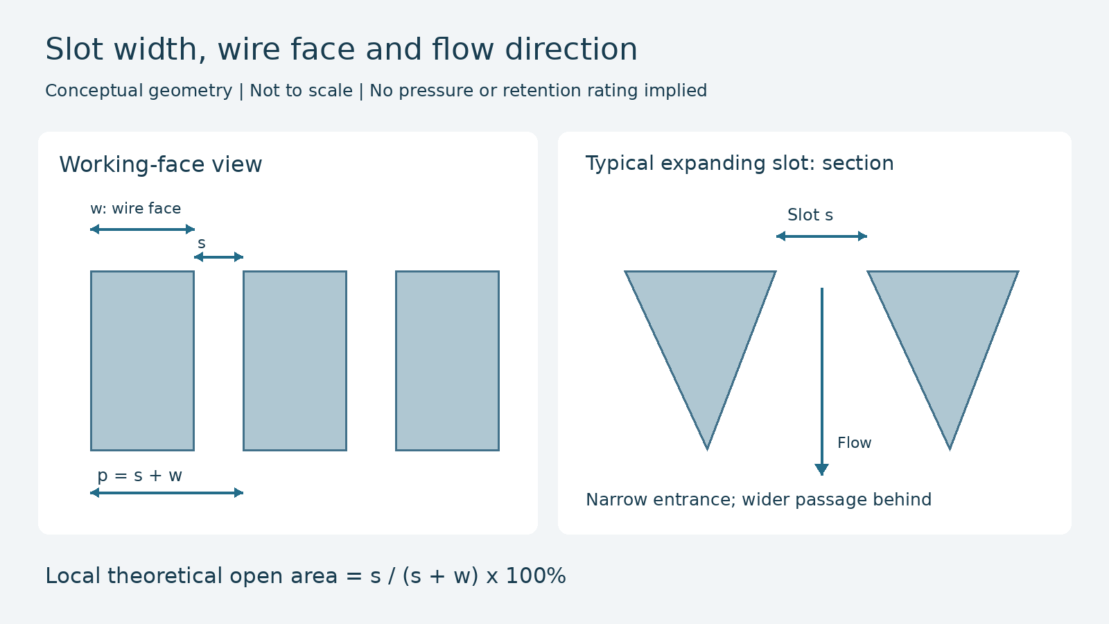
For a regular working face with parallel, repeating wires and slots, define clear slot width s, wire face width w, and pitch p. The simplified geometric relationship is p = s + w, with all dimensions in the same units.
Here, w is the width occupied by the wire at the working face. Wire height and the width of support bars are separate dimensions and cannot be substituted into this relationship.
| Parameter | Meaning | Measurement reference |
|---|---|---|
| Clear slot width s | Opening between surface wires | Slot entrance at the specified working face |
| Wire face width w | Width occupied by a surface wire | Same direction as the slot-width measurement |
| Pitch p | One repeating wire-and-slot length | s + w for the regular arrangement |
| Wire height and support dimensions | Section and support geometry | Recorded separately from working-face width |
A slot-only specification identifies opening size. Understanding open area also needs the face width; reviewing support and loading needs the wire section and support structure.
Relate the wedge section to flow direction
A typical wedge wire arrangement forms a narrow opening at the working face and a passage that expands in the intended through-flow direction. This can reduce opportunities for particles to become wedged deeper in the passage. Surface coverage and actual plugging still depend on feed and operating conditions.
For cylindrical screens, outside-to-inside and inside-to-outside flow can require different working-face and section arrangements. A cylindrical shape alone does not identify the intended direction.
Paragraphs [0030] and [0031] of European patent EP 3801822 B1 describe two arrangements with passages expanding in different through-flow directions.[1] They illustrate the relationship between section and direction; the confirmed drawing defines the actual product.
Also distinguish flow along the screen surface from flow through its slots. Some screening equipment has both. Show surface movement, rinsing or scraping direction separately where relevant, and relate the working face, normal filtration direction and cleaning direction to the same section.
Why equal slots can give different open areas
For the regular repeating region, theoretical local open area follows directly from one wire-and-slot unit:
Local theoretical open area = s / (s + w) × 100%
This estimates the area ratio of regular, parallel slots. It does not yet deduct frames, support obstruction or other closed regions.
Consider two hypothetical structures with the same 0.20 mm clear slot:
| Geometric example | Calculation | Local theoretical open area |
|---|---|---|
| s = 0.20 mm; w = 1.00 mm | 0.20 / 1.20 | About 16.7% |
| s = 0.20 mm; w = 2.00 mm | 0.20 / 2.20 | About 9.1% |
The slot widths match, but different proportions of the repeating surface are open. These are geometric examples, not product test results. They do not imply that flow capacity changes by the same ratio.
When comparing quotations, ask whether the wire face and active area match as well as slot width. Pressure loss and throughput require information about the complete construction, fluid and operating conditions.
Surface wires also have a structural function. Reducing their width to increase open area may change the section and manufacturing arrangement, so support, loading and service requirements need to be reviewed together.
Local open area and the complete component
Open area can use different denominators. State the area boundary before comparing percentages.
Local theoretical open area concerns the regular wire-and-slot region. A complete screen also includes unslotted edges, ends, seams and mounting features. Calculate its net opening area from the actual drawing.
For example, suppose a flat component has a total area of 0.50 m², with 0.40 m² of slotted region. At a local open area of approximately 16.7%, and before other obstruction, net opening area is about 0.0667 m². That is about 13.3% of the complete area. The two percentages describe different boundaries.
Deduct only the openings actually blocked by supports. A support bar's projection may cross both wires and slots; its entire projected area is not automatically lost opening area. Do not deduct an unslotted edge twice.
For a cylindrical screen, use the diameter of the actual screening face and its effective length, stating whether ends are included. Inner and outer working faces have different diameters, so using outside diameter for both loses that distinction.
The wedge wire slot and open area calculator separates local open area, slotted region and known opening obstruction. Complex supports, irregular shapes and actual edge-slot counts may need drawing-based calculations.

Slot geometry and particle retention
Slot width establishes a geometric scale. Retention also depends on how particles approach and pass through the opening. A particle-size name alone may not describe the size distribution or shape that matters.
A long particle can have a short axis smaller than the slot even when its length is larger. Orientation can therefore affect passage. Deformable and rigid particles also need separate consideration.
When a requirement states “0.20 mm,” establish whether it means nominal clear slot width or a retention proportion at a specified particle size. The former becomes a dimensional requirement with tolerances. The latter needs an appropriate performance-evaluation method. Unit conversion does not provide that validation.
Plugging also needs context. The U.S. Bureau of Reclamation's fish-screen research project 626 included debris type, concentration and hydraulic conditions in its research design, together with flow along and toward the screen.[2] These variables show why slot shape alone does not determine operating behaviour; the project is not a universal industrial plugging rule.
Keep two related records: slot geometry and permitted variation; and target particles, fluid, flow and required evaluation results. Clear evidence for each makes suitability discussions more useful.
Express slot requirements for manufacturing and inspection
An actionable requirement states how wide the opening should be, where it is measured and how much variation is permitted.
After the nominal slot value, define working face, measurement direction, tolerance, inspection region, sampling or measurement locations, and method. If local maximum openings matter, specify them rather than relying only on an average.
Choose a method suited to the opening scale and access. Suitable gauges may be evaluated for accessible larger slots; smaller or less accessible openings may need optical methods. Resolution, contact and decision rules must support the requirement without changing the opening during measurement.
| Acceptance subject | Information to define | What the result establishes |
|---|---|---|
| Slot geometry | Nominal width, tolerance, face, locations and method | Whether measured openings meet the agreement |
| Surface wire and supports | Section, spacing, construction and joining | Whether the structure matches the drawing |
| Finished fit | Dimensions, direction, interfaces and flatness | Whether installation follows the specified relationship |
| Filtration or operating performance | Particles, fluid, flow and acceptance conditions | Whether the task is met under the defined conditions |
Specify the final object being accepted after forming or rolling. Where the requirement applies to a delivered cylinder, the inspection plan should explain how measurements on the original flat panel support acceptance of that finished working face.
Filtalloy's wedge wire screen products include different forms and flow arrangements. Provide slot width, wire section, supports and working direction together when discussing custom requirements.
Frequently asked questions
Is 0.20 mm finer than 200 μm?
They are the same length. For filtration comparisons, also establish whether both mean clear slot width or whether one is a rating from a specific test method.
Does halving the slot width halve throughput?
That proportion is insufficient. Even at fixed wire face width, geometric open area follows s / (s + w). Actual throughput also depends on the complete structure, fluid and operating conditions.
Can one acceptable slot measurement represent the whole screen?
It first describes the measured location. Whether it supports acceptance of the complete component depends on the agreed sampling and decision plan, especially where local maximum openings matter.
Can a measured used slot become the new-part requirement?
Record it as the used component's measured condition and consider wear, deformation and deposits. To recover the original nominal requirement, use the original drawing, unused spares or traceable records where available.
Connect geometry to a usable specification
Read slot geometry, working-face direction and area boundary together. Then define dimensional acceptance separately from particle-retention evaluation. A specification can then support calculation, manufacture and sample confirmation on the same basis.
Send Filtalloy your specification or drawing with working face, flow direction, particles and service requirements. For an ion-exchange application, the related resin trap screen guide explains how to define the retention task.
Technical references
1. European Patent Office, EP 3801822 B1, August 3, 2022, paragraphs [0030]–[0031]. Original publication. Cited for section and flow arrangements.
2. U.S. Bureau of Reclamation, project 626, Design of Low Maintenance Water Diversion Fish Screens, funding years 2004–2005. Official research description. Cited for research variables, not a claim of universal completed test results.