By Jack Sun · Filtalloy, Anping, Hebei, China · October 19, 2026
A screen pack in an extruder needs a defined melt flow direction, a function for each mesh layer, and a clear relationship with the equipment support. A layer record with these details, followed by mesh specifications, finished dimensions and joining requirements, gives manufacturing and inspection a shared basis.
When you want an existing pack reproduced, the easiest information to supply is its outside diameter, number of layers and finest mesh count. The next questions are often about orientation, which side carries the coarse mesh, and whether the edges are bound or spot welded. These details matter: the same mesh pieces can form different components when their positions and installation relationships change.
Filtration layers, support mesh and the breaker plate
A pack has to address both retention and support. The filtration layer performs the specified particle-retention task. Its weave and passage structure help define the filtration requirement. Support mesh works with that layer to limit deformation and transfer load toward the equipment support. The breaker plate or screen seat belongs to the equipment and defines the installation and load-support boundary.
| Part | Function | Information to define |
|---|---|---|
| Filtration layer | Target particle retention | Mesh construction and the meaning of its filtration rating |
| Support mesh | Support for adjacent mesh | Position, mesh specification and contact with adjacent layers |
| Upstream coarse mesh, if used | Protection, support or coarse pre-screening as designed | Actual function and layer position |
| Breaker plate or screen seat | Installation and load support | Hole pattern, support face and mating dimensions |
Koller, Paulik and Burgstaller found that screen-pack deformation affected retention in their polypropylene melt-filtration experiments; an additional backing plate helped reduce deflection.[1] The practical point is to review the support beneath a fine mesh alongside its specification. Their results concern particular screens and test conditions, so the actual equipment still needs its own structural review.
A breaker plate does not automatically resolve every local support issue. The fine layer still spans openings in the supporting structure. Whether intermediate mesh is needed, and which construction to use, depends on the hole pattern, mesh layers and loading.
Describe layer order from the melt flow direction
Start from an explicit direction reference. “First layer,” “front” and “back” can mean opposite things to the manufacturer and equipment user unless they are defined.
Mark the melt inlet and outlet sides on a section, number the layers in the flow direction, and show the breaker plate. Keep any separate assembly datum on the drawing so the two references can be related.
For example, a three-layer arrangement might identify L1 as upstream coarse mesh, L2 as the filtration layer and L3 as downstream support mesh, followed by the equipment support. This illustrates a labelling method; the equipment design and filtration task determine the actual layer count, functions and order.
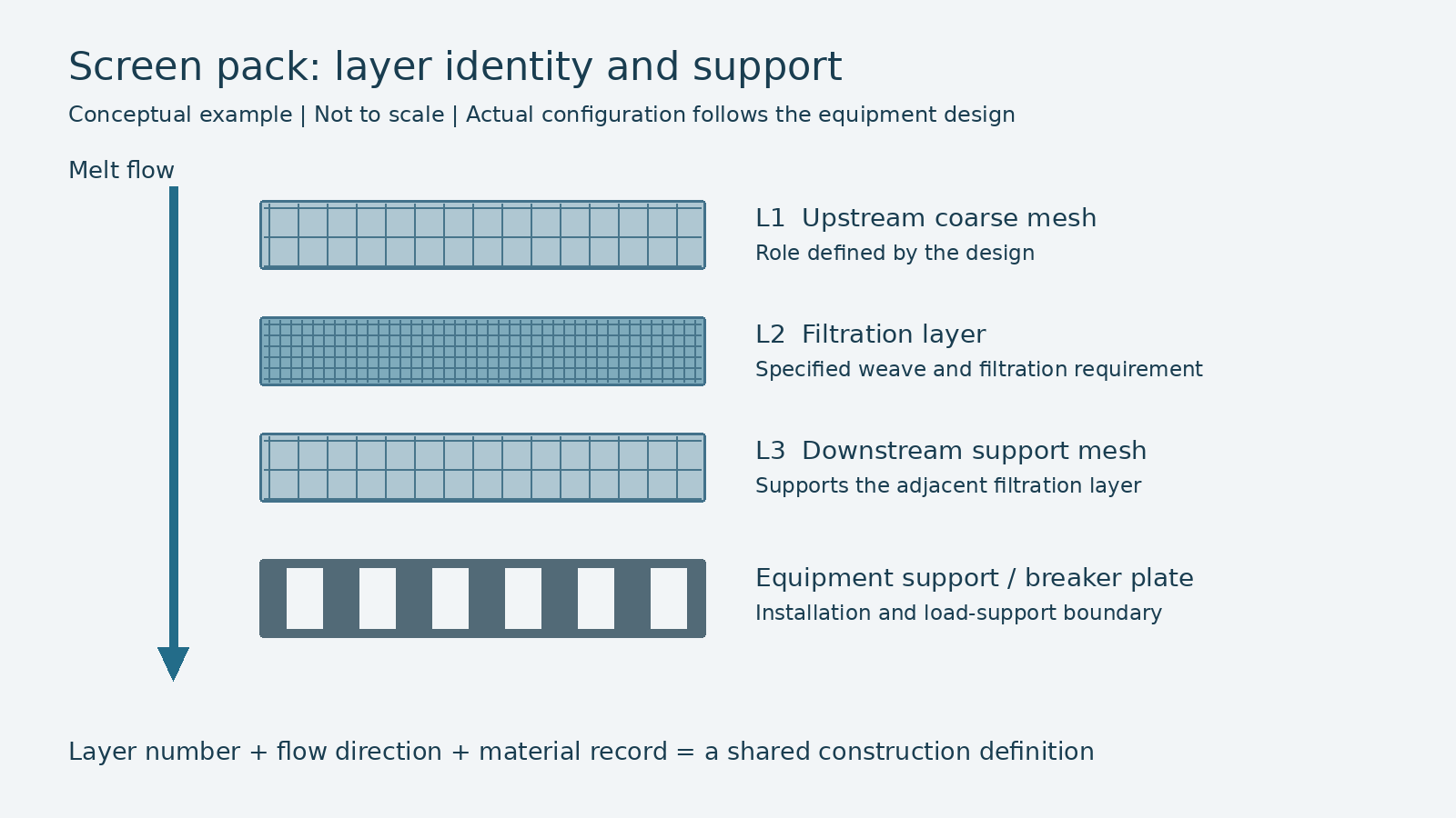
“Coarse to fine” describes some filtration arrangements but does not define an entire pack. Coarse mesh that supports a fine layer may sit downstream of it; arranging every layer by mesh count alone misses that function.
Bennett and colleagues analysed filtration layers, upstream and downstream support screens, and the supporting geometry together. Under their experimental and modelling conditions, the filtration layer's position relative to the support affected pressure-drop prediction.[2] A layer record therefore needs to state where each mesh sits as well as what it is.
This also explains why reversing a pack needs confirmation. Where the two sides have different structures or functions, turning it over changes their relationship with the incoming melt and support. Similar appearance does not establish equivalent performance in both directions.
Record the specification of every layer
Once positions are defined, link each layer number to a material specification. “Three layers of stainless steel mesh” or a single finest mesh count is not enough to reproduce the construction.
For square woven mesh, record mesh count and wire diameter together: the same count with different wire diameters can give different clear openings. ASTM E2016-22's public scope also distinguishes opening and wire-diameter specifications.[3] The wire mesh size calculator can help check square-mesh geometry.
Dutch weave needs separate warp and weft counts and wire diameters, weave type and the basis of its filtration rating. Its passages cannot be treated as ordinary square openings. See the plain and twill Dutch weave guide for the distinction.
| Record | What to include | Why it matters |
|---|---|---|
| Layer identity | L1, L2 and L3 matching the section | Connects the material list to the assembly |
| Material and weave | Specified grade and square or Dutch weave | Replaces vague descriptions such as “fine stainless mesh” |
| Woven specification | Count and wire diameter, or warp/weft data | Distinguishes similar-looking materials |
| Shape and dimensions | Each layer's outline, dimensions and agreed tolerances | Defines cutting and positioning |
| Condition and revision | New or used sample, calendering condition and drawing revision | Separates the original requirement from service changes |
Record a filtration rating separately and explain whether it describes geometric openings or a result under a specified test method. A micron label does not replace the manufacturing specification of every layer. The micron rating and efficiency guide explains the terminology.
Layer-by-layer records also make later substitutions easier to identify without redefining the entire pack.
Spot welding, edge binding and installation dimensions
Loose layers, spot-welded packs, bound edges and sintered assemblies are different constructions. Specify which one is required.
Spot welds help maintain layer order and relative position. A drawing can define weld locations, number or distribution, and the permitted affected area. For edge binding, specify the material, section and finished edge dimensions, including which dimensions are measured after binding.
Fixing layers together and controlling bypass are separate requirements. Weld points alone do not establish that melt cannot pass around an edge. A bound edge must also be reviewed against the equipment's mating surfaces and clamping arrangement.
Check total thickness, bound-edge height, flatness and the actual supported area as well as outside diameter. Define thickness measurement locations where welds or binding create local increases. Adding a layer may provide support while also changing installation space and the flow path; review the complete component after the change.
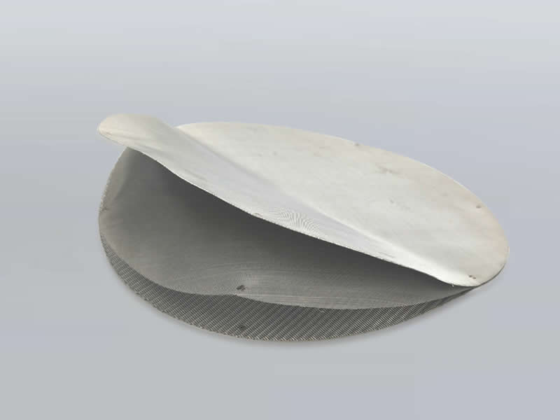
Filtalloy's extruder screen product page shows spot-welded and edge-bound forms. Orders are manufactured to the agreed structure and dimensions.
Turn an old sample into manufacturing information
Preserve the assembly background before separating a sample. Mark its original installation direction and photograph both faces and the edge. Where separation is permitted, number layers in their original sequence. Equipment procedures govern removal and disassembly; the purpose here is to preserve useful handover information.
Keep service deformation, deposits and wear separate from original design requirements. A bulged used pack can show its service condition, but copying the bulged thickness could reproduce an abnormal condition in a new component.
For an illustrative example, suppose a three-layer sample has a known diameter and middle-layer specification. Record those facts, then list the unknown flow direction, outer-layer specifications and measurement location for total bound thickness. Use equipment drawings, an unused spare or a sample that can be separated to resolve them. This is an information-completion example, not a customer case.
Reproducing a sample and improving performance also require different information. For plugging, breakage or product-contamination problems, supply operating records and define what the change should improve. The polymer melt filtration article provides broader operating context.
Sample confirmation and delivery acceptance
Drawing checks establish what was made; operating evaluation establishes how it behaves in the equipment. Connect both records to the same sample and revision.
| Stage | Focus | Useful record |
|---|---|---|
| Before assembly | Materials and weave specifications | Inspection records identified by layer |
| Finished component | Order, outline, thickness, edges and fixing | Drawing revision, dimensions and appearance |
| Installation | Direction, fit, clamping and support | Assembly confirmation and unresolved items |
| Operating evaluation | Initial resistance, trends and filtration results | Conditions, pressure, output and sampled results |
Agree inspection of hidden inner layers before assembly. When comparing old and new packs, keep polymer, feed condition, output, actual melt temperature and measuring locations as comparable as possible, and record any differences.
State the pressure measurement boundary. Upstream pressure can show trends under a consistent boundary; reporting differential pressure across a pack also needs downstream pressure and defined tap locations. Allowable differential pressure and change conditions depend on the equipment and confirmed pack construction.
Agree dimensions, layer order, appearance, operating evaluation and responsibility for reviewing deviations before sampling. Transfer the final revision, inspection requirements and change record into production after acceptance.
Frequently asked questions
Does a five-layer pack always filter finer than a three-layer pack?
No. Additional layers may provide support or protection. Identify the filtration layer and the meaning of its rating, then evaluate the complete structure in the actual melt.
Can coarser wire replace the same mesh count?
Treat this as a structural change. Wire diameter affects square-mesh openings and geometry, thickness and assembly relationships. Review support, adjacent layers and evaluation requirements together.
Is direction identification needed if the two faces look alike?
If the drawing specifies direction, the delivery identification needs to match it. Use agreed packaging, labels or permitted marking positions; direct marking depends on the structure and cleanliness requirements.
Is a spot-welded pack a sintered pack?
No. Spot welding connects layers at selected locations, while a sintered construction involves sintered bonding between layers. State the actual joining process and finished requirements.
Can a cleaned used pack serve as an accepted reference?
It can be a used sample with a known history. Using it as an accepted reference requires confirmation of its cleaned condition, structure and relevant performance, with a defined comparison scope. Original dimensions and filtration performance cannot simply be inferred from a used part.
For more detail on connection duties and seam acceptance, see wire mesh welding for filter components.
From a layer drawing to an agreed component
Begin with a drawing that shows flow direction, each layer's function and specification, fixing, mating surfaces and delivery checks. These relationships give manufacturing, sample reproduction and later changes a common basis.
Send Filtalloy your drawing, used pack or unused spare with the installation direction, layer information and the problem you want to address.
Technical references
1. Koller, K.; Paulik, C.; Burgstaller, C. Influence of material contamination on polypropylene melt filtration using assembled and fused screens. SPE Polymers, 2022, 3(1), 12–24. DOI: 10.1002/pls2.10061. Cited for deformation and backing-support observations, not operating pressure limits.
2. Bennett, J. D. et al. Computational modelling and experimental validation of pressure drop through multi-layered woven screens for polymer melts. Chemical Engineering Research and Design, 209 (2024), 323–333. Original research record. Model parameters and test flows are not presented as equipment requirements.
3. ASTM E2016-22, Standard Specification for Industrial Woven Wire Cloth. Official public scope. The public description supports specification terminology; it does not establish compliance of Dutch weave or a complete screen pack.