By Jack Sun · Filtalloy · October 19, 2026
Hold a piece of woven wire mesh up to the light and the openings are the first thing you notice. Look more closely and the wires rise and fall where they cross. The mesh is a woven structure, with a surface shaped by those crossings.
The openings are formed by the arrangement of the wires. Wire condition, warp preparation, tension, weft placement and the coordinated movements of the loom all contribute to the finished mesh.
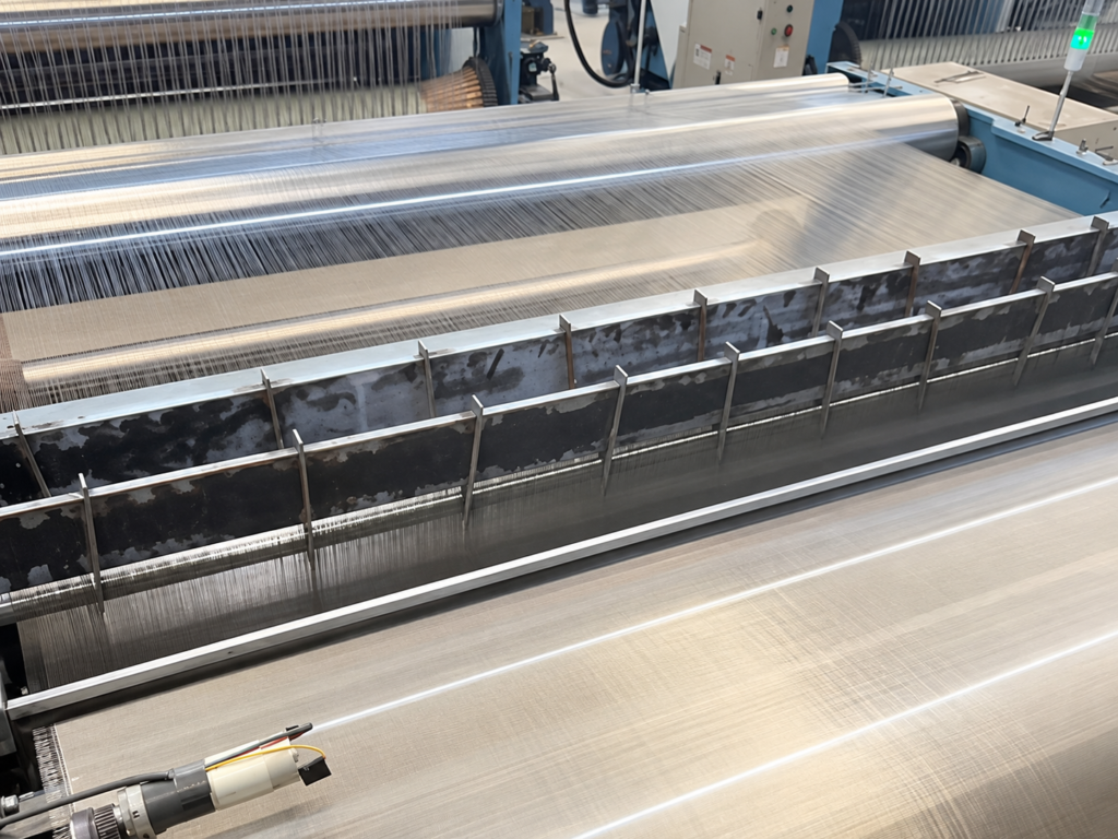
The woven wire mesh manufacturing process follows a clear sequence: prepare the wire, arrange the warp, thread and set up the loom, weave, inspect and carry out any required finishing. Following that sequence also helps explain why loose wires, bands, distorted openings or damaged edges can appear.
Warp, weft and openings: the starting structure
Wires running along the weaving direction are called warp wires. Wires introduced across the width are called weft wires, also known as shute wires. A loom interlaces these two sets in a selected pattern. [1]
In plain square weave, a weft wire passes over one warp wire and under the next. The following weft follows the opposite sequence. Bends around the crossings help the wires constrain one another and form a coherent mesh. [17]
Regular bending at the crossings is part of the weave. A sharp crease from handling or an isolated slack wire has a different origin.
Twill changes the crossing sequence. Dutch weaves use different combinations of wire diameters and counts to create a different internal passage structure. Similar-looking metal fabrics can therefore have quite different surfaces and flow paths. This article mainly follows common fine-wire mesh roll production; a visible square opening is not a model for every weave.
Why spacing and wire diameter both matter
For regular, uncoated square mesh, the pitch is the distance between the centres of adjacent wires. Subtracting the wire diameter from that pitch gives the theoretical clear opening in that direction.
Consider an illustrative 50-mesh arrangement. Its theoretical pitch is 25.4 ÷ 50 = 0.508 mm. With a 0.20 mm wire, the calculated opening is about 0.308 mm. With a 0.25 mm wire, it is about 0.258 mm. These are geometry calculations, not measured production results. [16]
The example explains why equal mesh counts do not necessarily mean equal openings. It also explains why manufacturing has to control both wire size and arrangement. The calculated opening is neither a measurement of every opening in the finished cloth nor a filtration-efficiency rating.
See the Dutch weave guide for structural comparisons and mesh count versus micron opening for the relationship between count, diameter and aperture.
Wire preparation: repeated bending starts with the wire
Before it becomes mesh, wire travels through guides, carries tension and bends at the crossings. Its surface and mechanical condition therefore matter alongside its diameter. Drawing and annealing can change wire condition; the required condition has to suit the material, diameter and weave. [2]
Small surface damage can matter during weaving
A scratch, kink or locally damaged area may be difficult to see from a distance. When the wire subsequently carries load and bends, that area may become a weak point.
Repeated breaks at similar locations call for more than the explanation that a wire is too fine. Possible contributors include the incoming surface, contact at a guide, local friction and abnormal tension. Wire condition and the machine's contact conditions need to be considered together.
This is why organising reels and wire paths has a technical purpose. A snag, crossed wire or sudden pull interrupts an otherwise continuous feed. A loose or broken wire at the weaving area may have its origin further back in the supply path.
Softer and harder are not complete weaving specifications
A wire that bends easily does not suit every structure, and a harder wire does not automatically produce a more stable mesh. Formability, support and subsequent processing need to be considered together.
A tight weave still requires the wire to complete its intended bends. If local weaving loads exceed what the wire can tolerate reliably, damage can occur. No single instruction to maximise hardness or strength can replace matching the wire to the structure.
The question at this stage is weavability: can the wire feed smoothly, withstand the weaving motions and form the required structure? Drawing and annealing may take place at a specialist wire producer. They are not necessarily performed inside every weaving factory for every mesh roll.
Warping: arranging many wires into an orderly feed
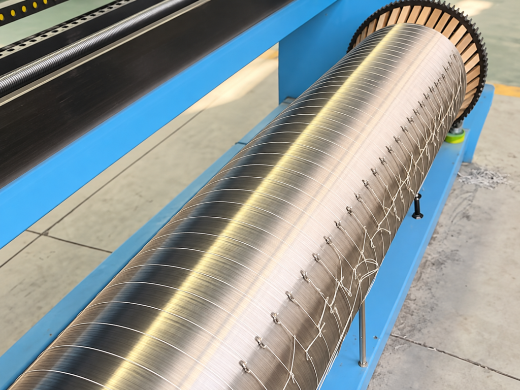
Warping organises individually supplied wires into the longitudinal set used by the loom. With a common beam-fed arrangement, wires are ordered and wound onto a warp beam before being introduced to the loom. Other feeding arrangements depend on the equipment and mesh. [3]
From a distance, warping can look like neat winding. It also prepares wire paths and loading conditions for what follows.
Parallel wires can still carry different loads
Two warp wires may look parallel while behaving differently in motion. One may feed freely while another encounters greater resistance at a guide.
A slack wire can move in unwanted ways during shedding and weft insertion. Excessive tension or concentrated loading can increase the risk of damage and breakage. The useful questions concern a suitable tension range, consistency across the warp and changes during running. General weaving principles likewise link stable warp and fabric tension with smooth, even fabric formation. [4]
A locally slack wire, uneven opening or raised area in the finished mesh may be related to loading differences. Appearance alone does not identify warping as the cause: guides, loom movements and take-up also need consideration.
Crossed paths and snags disturb the feed
Wires intended to follow separate paths can encounter extra friction if they cross, snag or bind. The loom continues to shed and advance the fabric while an affected wire fails to follow smoothly, changing its local loading.
Preparing the warp therefore includes making sure the wires remain orderly during motion. With fine structures, a small local disturbance can be significant to the appearance of the mesh that follows.
Threading and trial weaving: turning arrangement into a pattern
Prepared warp wires must pass through the components that control their movement and lateral arrangement. Two useful terms are heddle and reed.
Heddles help control which warp wires rise or fall. The reed provides spaces through which warp wires are arranged and helps push each new weft towards the forming mesh. The threading arrangement and movement sequence contribute to the weave pattern. [5][6]
Incorrect threading and a missing wire are different problems
A wire threaded into an unsuitable control position can move differently from the intended sequence. The result may be a longitudinal pattern irregularity rather than a conspicuous hole.
A missing warp wire changes the local arrangement and opening shape. Both situations can produce a visible strip, but one concerns crossing sequence and the other missing wire. They require different explanations.
The distribution of wires through the reed also affects their lateral positions. A persistently wider row of openings warrants examination of the threading, associated components and local loading. Changing the overall weft count alone does not explain every such mark. [7]
Trial weaving checks the result of the setup
Trial weaving allows the actual structure to be observed after threading and setup. Useful observations include the crossing sequence, stable wire arrangement, openings and edge behaviour. Published manufacturing descriptions place warp adjustment and trial weaving before full production. [8]
The relevant result is the mesh being formed under stable running conditions, rather than a small area pulled flat for a moment. Running, stopped and relaxed mesh can present different states.
If the problem comes from threading or crossing sequence, producing more length will not make it disappear. Establishing the correct structure before checking running stability helps separate these problems.
Weaving: shedding, insertion, beat-up and take-up
Three repeated motions are readily identifiable: shedding, weft insertion and beat-up. [4]
Shedding opens a path for the weft
The warp wires move into selected upper and lower positions, leaving a passage called the shed. Its opening has to work with the wire, the machine and the insertion system.
If the passage and insertion timing are poorly coordinated, the weft may meet an obstruction. In that situation, wire position and movement coordination deserve attention alongside incoming wire condition.
Weft insertion introduces the crosswise wire
The insertion system carries the weft across the width through the shed. Industrial wire mesh looms can use different insertion systems; one mechanism does not describe every machine. [9]
The length and position of the inserted wire need to coordinate with subsequent motions. Incomplete insertion, local slack or a bent weft can contribute to irregular placement, enlarged local gaps or unevenness. Each observation still requires examination of the particular machine and mesh.
Beat-up places the weft at the forming fabric
During beat-up, the reed moves the new weft towards the cloth fell, where the mesh forms. Take-up advances the woven material so the next weft can occupy its intended position. [4][6]
Weft count can be understood through this relationship. The same number of weft wires spread over a greater finished length produces a more open arrangement; spread over a shorter length, they are closer together. Density involves coordinated formation and advance, rather than simply hitting the weft harder.
Starting, stopping or adjusting a loom can change the local running state. If motion and loading have not stabilised, a section may show a spacing difference. The appearance and causes depend on the equipment; not every crosswise band should be assigned the same explanation.
Why the woven wires have regular bends
The wires bend around one another at crossings, forming crimp. This helps explain why overall mesh thickness is not simply the diameter of one wire. It also helps explain why loading a mesh may change the crossing geometry as well as stretch the metal itself. [1]
Some coarse meshes use wires crimped before weaving. This article follows common fine-wire roll production; pre-crimping, welding and perforating are distinct manufacturing routes.
Observing the process: bands, slack wires and opening shape
Useful observations include the direction of an irregularity, whether it repeats, whether it occurs at an edge or in the middle, and how it differs from the surrounding structure.
The following links are possible mechanisms to investigate, not a diagnosis from appearance alone. [7]
| Observation | Technical areas to consider | Possible effect on the mesh |
|---|---|---|
| A raised or slack warp wire | Warp loading, feed resistance, local contact or path differences | The wire's shape and neighbouring openings may differ |
| A locally sparse or dense weft arrangement | Insertion, beat-up, take-up and running state after a stop | Local pitch and mesh uniformity change |
| A longitudinal row of unusual openings | Reed distribution, warp arrangement, local loading and component condition | A repeated difference can form a visible strip |
| A missing or broken wire | Local wire damage, friction, abnormal loading or a weaving fault | Interlacing becomes discontinuous and local restraint is lost |
| A local change in crossing pattern | Threading, movement sequence or an interlacing fault | Wires remain present but the structure differs |
An average does not describe every local opening
An average count close to the intended value can coexist with local differences. A wider space and a narrower space may partly offset in an average while both remain present.
Dimensional checks and visual observation provide different information. Measurements describe diameter, pitch, opening shape or thickness. Observation helps reveal bands, isolated slack wires and surface damage. Neither completely replaces the other.
Flatness and correct structure need separate attention
Roll curvature, a sharp crease, a slack wire and an incorrect crossing pattern can all affect how flat a mesh looks. They have different mechanisms. Grouping them together can create the mistaken expectation that subsequent calendering will resolve them all.
The woven wire mesh defects guide examines irregularities in more detail. Here, the purpose is to relate them to the manufacturing sequence.
Finishing: cleaning, calendering, heat treatment and cutting
Mesh can be supplied in its woven condition or processed further. The combination and sequence depend on material, structure and use. Every roll does not require every finishing operation. [10]
Cleaning deals with surface deposits
Fine deposits or processing residues can remain after weaving. Additional cleaning may be used where a cleaner surface is required. [11]
The method has to be compatible with the material, while handling and support protect fine mesh. A cleaner surface does not demonstrate that broken wires, incorrect crossings or opening irregularities have been repaired. Subsequent coating or welding may also require a particular surface condition.
Calendering changes thickness and crossing geometry
Calendering passes the mesh through rolls to change thickness and surface form; it can also change mechanical behaviour. It is a purposeful process with effects that need to be assessed. [12]
One way to understand it is to compare the original height of the crossings with their form after rolling. Thickness needs to be checked afterwards. Where opening geometry or passage structure matters, thickness alone is not a complete assessment.
Calendering cannot replace a missing wire or rearrange an incorrect crossing sequence. Slack wires and creases likewise require an understanding of their origin rather than an assumption that rolling will solve them.
Heat treatment needs a defined purpose
Annealing and other heat treatments can adjust properties relevant to forming. Their effect depends on the material, route and intended result. Ordinary annealing should not automatically be described as creating sintered bonds at every crossing. [13]
Improving forming behaviour and bonding crossings are different objectives, even though both can involve heat. A temperature, holding time or atmosphere detached from the particular material and structure is not a reliable general processing instruction.
Cutting creates a new boundary
Slitting rolls, cutting sheets or punching discs severs some of the wires. The new edge has different restraint from the continuous interior. Loose wires, fraying and local distortion therefore need attention. [14][15]
Cutting quality involves more than blade sharpness. Support, tooling and cutting method can affect whether the mesh is dragged, openings skew or an unsupported edge lifts.
A woven selvage and a newly slit edge are different structures. Slitting does not automatically reproduce the restraint of the original selvage. Edge binding, welding or another restraint may be useful for a particular application, but every exposed cut edge is not inherently defective.
For methods and edge behaviour, see how to cut wire mesh.
Unrolling and winding: handling still affects the mesh
A finished roll includes both its woven structure and its condition when opened. Local folding, crushing or pulling after weaving can introduce new damage.
Rolling bends the material over a continuous radius. A sharp crease concentrates deformation into a narrow region. Their behaviour after unrolling can differ, and pulling the mesh flat is not a universal remedy.
Inspection should distinguish naturally relaxed mesh from material pulled by hand or tensioned in a frame. External force can temporarily hide unevenness while changing the visible openings. Repeated pulling can therefore interfere with understanding the original state.
Where thickness, dimensions or opening geometry have a defined function, an appropriate measurement method and condition are needed. There is no single allowable value that applies to every weave, material and use.
Manufacturing stages and technical issues at a glance
| Stage | Technical focus | Possible consequence of a disturbance |
|---|---|---|
| Wire preparation | Surface condition, kinks, feed path and weavability | Irregular loading, friction damage or greater breakage risk |
| Warping | Orderly paths and consistent loading | Slack wires, local unevenness or opening differences |
| Threading | Control positions and lateral wire distribution | Persistent pattern irregularities or unusual opening rows |
| Weaving | Coordination of shedding, insertion, beat-up, let-off and take-up | Missing picks, density differences, broken wires or uneven fabric |
| Cleaning and heat treatment | Treatment purpose, compatibility and material condition | Existing structural problems remain, or additional surface/forming issues arise |
| Calendering | Thickness, surface and crossing changes | Appearance alone can hide changes needing further measurement |
| Cutting and winding | Support, edge restraint and local loading | Loose ends, fraying, lifting or creases |
Frequently asked questions
How do woven and welded mesh crossings differ?
Ordinary woven mesh is formed by interlacing and wire bends. Welded mesh has joints made at crossing positions. Woven mesh may subsequently be welded or sintered, but those are additional operations, not properties established by the name alone.
Why does metal wire mesh need threading?
The loom has to control groups of warp wires in a defined order and arrange them across the width. Threading establishes those paths. Simply laying many wires side by side does not create a controlled weave.
Will more tension make the mesh flatter?
Suitable tension supports stable weaving, but increasing it is not a general repair method. Incorrect threading, a snag, damaged wire or poor movement coordination may remain unresolved while local loading increases. Tension level, distribution and running stability are separate questions.
Does a visible band mean the openings are unacceptable?
A band alone does not establish that conclusion. Lighting, viewing angle and structural variation affect appearance. Enlarged observation and suitable measurements help distinguish optical effects from changes in spacing, wire condition or crossing pattern.
Does calendering turn woven mesh into sintered mesh?
Calendering applies mechanical rolling. Sintering involves bonding under a particular thermal process. A product can combine processes, but a flatter surface does not by itself establish metallurgical bonding at the crossings.
Does an even-looking mesh have uniform filtration performance?
Appearance and geometry help describe the material, but cannot alone establish efficiency, pressure drop or service life. Fluid, flow, assembly support, sealing and test method also matter. Manufacturing explains how the material forms; performance needs evidence under the relevant conditions.
Stable weaving is a chain of connected conditions: wires enter in an orderly way, the loom's motions work together and later operations preserve the structure as intended. Following that chain makes it easier to distinguish a slack wire, a density band, a frayed edge and a handling crease rather than treating them as the same flatness problem.
Technical references
1. Cleveland Wire Cloth — Wire Cloth Glossary: wire directions, weave terminology and crimp.
2. BOPP — From Raw Material to Fine Wire: drawing, annealing and wire condition.
3. BOPP — Warping: preparing warp wires on a beam.
4. U.S. National Park Service — How Does Weaving Work?: general weaving motions and tension; textile examples are not metal-mesh processing parameters.
5. NBC Meshtec — Mesh Cloth Production Process: threading functions; synthetic-fabric dyeing and heat-setting routes are not transferred to metal mesh.
6. U.S. National Park Service — Glossary of Weaving Terms: heddles, reeds, shedding, insertion and beat-up.
7. HAVER & BOECKER — Quality Control in Wire Mesh Manufacturing: examples of weaving irregularities.
8. ASADA MESH — Factory Tour: threading, adjustment, trial weaving and inspection stages.
9. BOPP — Weaving: different insertion systems.
10. BOPP — Fabrication: further-processing routes.
11. BOPP — Mesh Cleaning: deposits and additional cleaning.
12. BOPP — Calendering: changes to thickness, surface and mechanical properties.
13. BOPP — Heat Treatment: treatment objectives and routes.
14. BOPP — Cutting and Punching: cutting and edge quality.
15. BOPP — Cutting and Slitting: strip processing.
16. BOPP — A–Z of Mesh Technology: square-mesh geometry.
17. HAVER & BOECKER — Plain Square Weave: over-and-under crossing sequence.
These sources support general principles and terminology. Their equipment, proprietary processes, tolerances and performance statements do not describe our manufacturing capabilities.
Jack Sun has long worked in metal wire mesh weaving and industrial filter element manufacturing. Our company is based in Anping, Hengshui, Hebei, China.