Quick definition
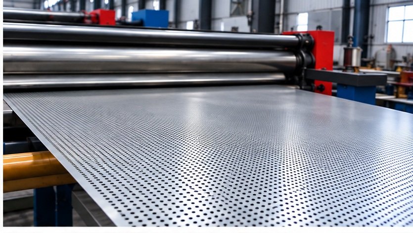
A perforated metal sheet is metal plate or sheet with a defined arrangement of holes produced by punching, laser cutting or another suitable process. Hole shape, size, pitch and pattern define the openings; thickness, material, margins and fabrication details define the complete part.
“304 stainless steel, 2 mm thick, 5 mm round holes” describes only part of an order. To quote and manufacture the right product, the supplier also needs the hole spacing, pattern, sheet dimensions, solid borders, tolerances, surface condition and any forming or welding requirements.
By Jack Sun. Our company is based in Anping, Hengshui, Hebei, China, a center for wire mesh manufacturing. Jack Sun has long worked in wire mesh weaving and industrial filter manufacturing.
Why perforated sheet metal inquiries often need more detail
A hole diameter alone cannot establish flow capacity, screening behavior, stiffness or manufacturing cost. Two sheets with the same holes can perform differently because their pitch, thickness, materials or unsupported dimensions differ.
Use a practical sequence: application → function → critical parameters → manufacturing review → complete specification. This guide follows that sequence for filtration supports, screens, ventilation panels, guards, acoustic structures, architectural panels and OEM parts.
1. Which parameters define a perforated metal sheet?
A complete specification normally identifies material grade, sheet thickness, hole shape, hole dimensions, center-to-center pitch, row arrangement, open area, sheet or coil dimensions, solid margins, finish, flatness, tolerances and secondary fabrication.
These parameters interact. Reducing pitch while holding diameter constant increases the perforated area’s theoretical open area and narrows the ligaments between holes. That can change stiffness, distortion and processing difficulty. Small holes in a thick or high-strength material also require a different tooling review from larger holes in thin sheet.
Specify the geometry directly. An open-area percentage by itself does not uniquely identify a hole size or pattern.
2. Set priorities according to the application
| Application | First priority | Second priority | Further checks |
|---|---|---|---|
| Filtration or filter support | Retention target or support function | Open area | Medium compatibility, thickness and differential pressure |
| Screening and classification | Hole size and shape | Dimensional consistency | Particle shape, wear and plugging |
| Ventilation and cooling | Flow requirement | Open area and mechanical strength | Pressure loss, noise and guarding needs |
| Machine guarding | Risk assessment and protective function | Opening dimensions and strength | Distance to the hazard and secure mounting |
| Acoustic assembly | Acoustic design | Hole size, open area and thickness | Backing cavity or absorbent structure |
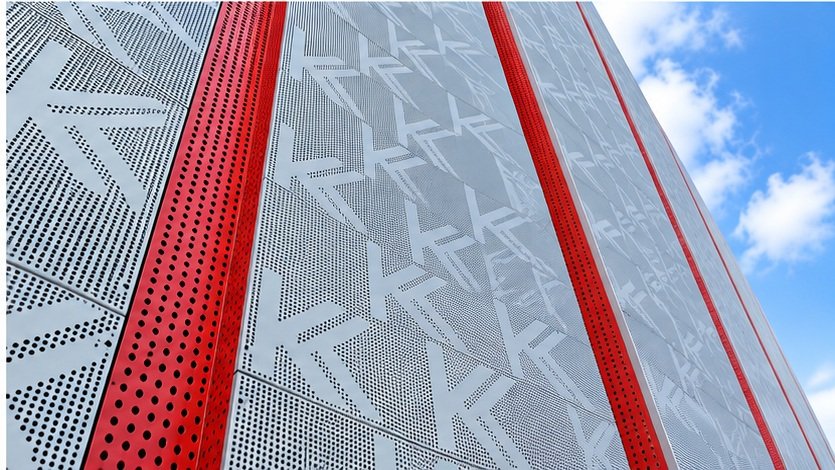
| Architecture and decoration | Appearance and structural duty | Pattern and finish | Flatness, fixing, exposure and panel dimensions |
| OEM component | Fit and tolerances | Manufacturability | Bending, welding and batch consistency |
Decide which requirements cannot be compromised before optimizing weight or cost. A screening plate should begin with the particles it must classify. A guard should begin with its protective function and the equipment risk assessment.
3. How to choose the hole size
Filtration and screening
Ask what must pass and what must be retained. Particle size distribution, shape, orientation and plugging behavior affect passage through an opening. A flat or elongated particle may pass differently from a rounded particle with a similar nominal size.
Hole diameter is not an absolute filtration rating. In fine filtration, perforated sheet often supports or protects wire mesh, sintered media or another filter layer. Evaluate the complete filter assembly rather than attributing its retention performance to the support plate.
Ventilation and cooling
Compare total available opening area, flow resistance, strength and any protective requirement. Many small holes are not automatically better than fewer larger holes. Open area is useful, but it is not a complete pressure-drop or cooling prediction.
Mechanical protection
Opening size and shape must be considered together with the distance to the hazard, guard strength and mounting. ISO 13857 addresses safety distances intended to prevent upper and lower limbs from reaching machinery hazard zones. A perforated sheet specification alone does not establish the safety of the complete guard.
4. Hole shape and hole pattern are different choices
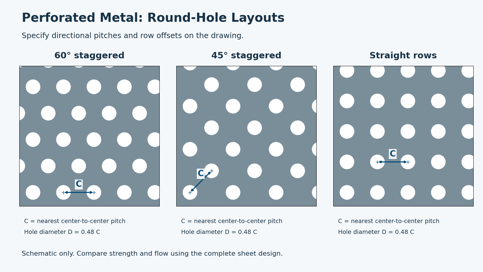
Hole shape identifies round, square, oblong, rectangular, hexagonal or custom openings. Hole pattern identifies their arrangement, such as straight rows or staggered rows. Describe both on the drawing.
Round holes
Round holes are widely used for industrial ventilation, screens, filtration supports and fabricated parts. Tooling availability can make them a practical starting point when the application does not require a different opening shape.
Square holes
Square openings provide a different geometry for screening or visual design. Equal nominal width does not make a square opening equivalent to a round one. Review corner geometry, tooling and the remaining material.
Slotted or oblong holes
Slots can suit elongated particles or directional flow and screening requirements. Specify width, overall length, end shape and orientation. A single “hole size” value cannot define an oblong opening.
5. Pitch determines the material left between holes
Pitch normally means center-to-center spacing. For adjacent equal round holes on the same centerline, the clear ligament width is C − D, where C is center pitch and D is hole diameter. For other patterns or directions, assess the actual drawing geometry.
At the same diameter, a larger pitch generally leaves more metal and reduces theoretical open area. A smaller pitch increases hole density and narrows the ligaments. Overall strength still depends on material, thickness, pattern, panel dimensions, support and load direction.
For staggered or rectangular layouts, identify the pitch in each direction and the row offset. Do not assume that a supplier’s single pitch value means the same measurement in every pattern.
6. Understanding perforated metal open area
Open area is the area of the openings divided by the area being considered, expressed as a percentage. Distinguish the theoretical percentage of a repeating perforated field from the percentage of the entire finished part.
Solid borders, fixing zones, bending zones and other unperforated areas reduce the finished part’s overall open-area percentage. Increasing open area also removes more metal, so flow, stiffness and manufacturing requirements should be reviewed together.
60° staggered round-hole formula
For a uniform triangular arrangement of equal round holes, using the nearest center-to-center pitch C:
OA (%) = 90.69 × (D / C)²
D and C must use the same length unit. The relationship comes from the area of a circular hole divided by the repeating cell area, (√3 / 2)C². With D = 5 mm and C = 8 mm, the theoretical open area is approximately 35.4%.
This formula applies to the specified 60° layout. It should not be applied unchanged to straight rows, arbitrary staggered patterns, slots or irregular designs. It also excludes the effect of solid margins.
Use our perforated metal open area calculator to compare patterns. For solid borders and other exclusions, use the perforated sheet effective open area calculator.
7. Sheet thickness and hole size: manufacturing limits
A hole that is easy to draw may be difficult to punch economically. Small punches working in thick or high-strength material can face demanding loads, reduced tool life and more difficult control of burrs or hole quality.
“Hole diameter must exceed sheet thickness” is not a universal rule. Some tooling and processes can produce smaller openings, but feasibility depends on material, thickness, diameter, spacing, tool support and quantity. Review small-hole, thick-sheet designs before freezing the drawing.
Tooling suitability does not establish our capacity for every geometry. The actual part must be assessed against the intended manufacturing route and acceptance requirements.
8. Choosing the perforated metal material
Select a grade for the environment, mechanical duty, weight, finish and fabrication route. A material family name is not a complete grade specification.
Carbon steel
Carbon steel can be an economical choice for industrial screens, guards and structural components. Where moisture or corrosive exposure is expected, consider an appropriate protective finish and its maintenance requirements.
304 stainless steel
304 is used in many industrial and equipment applications where its corrosion resistance and surface properties suit the environment. It can still corrode. Suitability for food equipment also depends on the complete equipment design, cleaning conditions and surface requirements.
316L stainless steel
316L contains molybdenum and can offer better resistance to localized corrosion than 304 in many environments. It is not universally suitable for chloride-containing service. Evaluate composition, temperature, exposure and cleaning chemicals before selecting the grade.
Aluminum
Aluminum can reduce weight in ventilation panels, equipment and architectural parts. Specify the alloy and temper because strength, forming behavior and finishing compatibility vary. Handling and fabrication should protect the surface and control deformation.
Copper
Copper may be selected for electrical, thermal or decorative requirements. Confirm the grade and final surface condition, including whether natural surface changes are acceptable.
9. Decide the surface finish before fabrication
Options may include galvanizing, powder coating, painting, aluminum anodizing, stainless steel pickling or passivation, and polishing. Specify the desired final condition and the sequence of punching, bending, welding and finishing.
Punching pre-coated sheet can expose the substrate at cut edges. Welding can affect the original finish. Coatings can also change opening dimensions, which matters for small holes or tight requirements. A 2B sheet finish does not mean punched edges and welds automatically retain the same surface condition.
10. Check design for manufacturability
Review the following before committing to batch production:
- Hole dimensions relative to thickness and material strength.
- Minimum ligaments, edge distances and clearance from bend lines.
- Pattern density, distortion risk and required leveling.
- Solid margins, mounting holes and permissible partial holes at cut edges.
- Available tooling, any special-tool cost and order quantity.
- Dimension, position, burr and flatness requirements.
- Forming, welding and surface treatment in the finished part.
Agree tolerances according to function and achievable production control. Do not add unnecessarily tight tolerances that have no assembly or performance purpose.
11. Punching versus laser perforation
Die punching or CNC punching
Punching mechanically shears the sheet between a punch and die. It can be efficient for repeated patterns and stable production quantities, especially when suitable tooling is available. Tool size, force, die clearance, tool wear and quantity all affect the manufacturing plan.
Laser cutting
Laser cutting avoids a dedicated punch for each opening shape and can suit prototypes, small batches, custom contours or changing patterns. It is a thermal process, so evaluate the cut edge, heat effects, dross and any finishing requirement.
A large sheet with many thousands of identical holes may be more economical to punch than to laser cut. Neither process is automatically superior. Compare material, thickness, geometry, quantity, edge requirements, tolerances, lead time and total processing cost.
12. Margins, flatness and secondary fabrication
Unperforated margins
Define the solid border on each edge and any internal solid zones needed for fasteners, welding, bends or frames. Specify whether partial holes at the sheet edges are permitted. An exact border and an exact repeating pattern may require a deliberate layout adjustment.
Mark the edge and centre references
For a complete round hole, label the clear edge margin e from the finished sheet edge to the nearest hole perimeter, and the centre offset c to that hole centre. Along the perpendicular direction, c = e + d/2, where d is hole diameter. For example, a 10 mm centre offset with a 4 mm round hole gives an 8 mm clear margin. These are illustration values, not required margins.
Mark left/right against sheet width and top/bottom against sheet length, then show pitch directions, staggered-row offset, internal solid zones and any permitted partial edge holes. For slots or other shapes, locate the actual nearest perimeter; do not substitute half an arbitrary “hole size”.
The sheet hole count calculator takes clear margins and anchors the first hole at the left/top margins. The effective sheet open area calculator estimates patterned area after blank bands and blocked zones. Use the layout drawing when the final number of complete holes or their exact edge positions matters.
Flatness
Punching can introduce residual stress and distortion. Thin sheet and dense patterns can need particular attention. State the required flatness, measurement method and inspection condition, including whether it applies before or after installation in a frame.
Cutting, bending, rolling and welding
If the final product is a cylinder, guard or formed OEM part, quote the finished component where possible. Plan holes and solid zones around bends, seams and mounting points. Forming can alter openings, and welding can affect alignment, flatness and finish.
13. Write a complete perforated metal specification
| Item | Example or information required |
|---|---|
| Material | 304 stainless steel, with the required grade specification |
| Thickness | 1.5 mm, with agreed tolerance |
| Hole shape and size | Round, 5 mm diameter |
| Pitch and pattern | 8 mm nearest center pitch, 60° staggered |
| Product dimensions | 1000 × 2000 mm sheets; or coil width, length and relevant coil limits |
| Solid zones | 25 mm border on all four sides, with edge layout shown |
| Surface condition | 2B starting surface; specify required edge and final treatments |
| Acceptance requirements | Hole, pitch, size, burr and flatness tolerances; agreed inspection method |
| Secondary fabrication | Cutting, bending, rolling or welding details on the drawing |
| Quantity and delivery | For example, 200 sheets, with packaging and delivery requirements |
Example inquiry: 304 stainless steel, 1.5 mm thick, 5 mm round holes, 8 mm nearest center pitch, 60° staggered pattern, 1000 × 2000 mm sheets, 25 mm solid margins on all sides, 2B starting surface, quantity 200 sheets. Confirm the layout, tolerances, burr requirements and final surface condition against the drawing.
This is an illustrative purchasing specification, not a stock-size or production-capacity commitment.
14. Common perforated metal selection mistakes
- Providing only diameter: include pitch, pattern and product dimensions.
- Maximizing open area alone: assess flow, mechanical duty and fabrication together.
- Pairing very small holes with thick sheet without review: check tooling and process feasibility first.
- Planning fabrication after the pattern is fixed: reserve solid zones for bends, welds and mounting.
- Choosing a material by grade hierarchy: use the actual environment and service requirements.
- Treating aperture as an absolute filter rating: evaluate the particles and the complete filtration assembly.
15. Frequently asked questions
What is the best thickness for perforated metal sheet?
There is no universal best thickness. Consider load, material, opening geometry, sheet dimensions, supports and fabrication. Structural and guarding duties may prioritize strength, while ventilation panels may also prioritize weight.
How do I choose perforated metal hole size?
Begin with function. Screening requires particle size and shape information. Ventilation requires flow and strength checks. Guarding requires the opening geometry and distance to the hazard to be assessed together.
What is open area in perforated metal?
It is the percentage of the considered area occupied by openings. Specify whether the value applies to the perforated field or the complete finished part with solid borders.
Can hole diameter be smaller than sheet thickness?
It can be possible with suitable tooling or another process. Feasibility and economic production depend on the material and complete geometry, so a manufacturing review is needed.
Is laser cutting better than punching?
The preferred route depends on pattern, quantity, material, thickness and edge requirements. Laser cutting can suit changing or custom designs; punching can be efficient for large quantities of repeated holes.
Which is better, 304 or 316L perforated stainless steel?
Choose according to the corrosion environment and fabrication duty. 316L can improve localized corrosion resistance in many conditions, but the grade name alone does not establish suitability.
16. Define the function before defining the sheet
Start by identifying what must pass, what must be stopped, the required flow, the mechanical load, the environment and the final part geometry. Then specify material, thickness, hole shape, hole size, pitch, pattern, open area, margins, tolerances, finish and fabrication.
For small holes in thick material, high open area, custom patterns or demanding flatness, arrange a manufacturability review before freezing the drawing or ordering the production batch.
Contact our engineers
Send your drawing, sample or existing specification so we can review the material, holes, spacing, thickness, open area and manufacturing route. Describe the final application and any assembly or performance requirements.
Get a custom solution
For sheets, coils, perforated tubes, filter supports, guards or OEM components, define the finished product and the required processing. Explore our perforated sheets and perforated tubes.
Technical references
- ISO 13857:2019 — safety distances for machinery hazard zones.
- TRUMPF punching tools technical catalog — tooling considerations, including guided tools for openings smaller than sheet thickness.