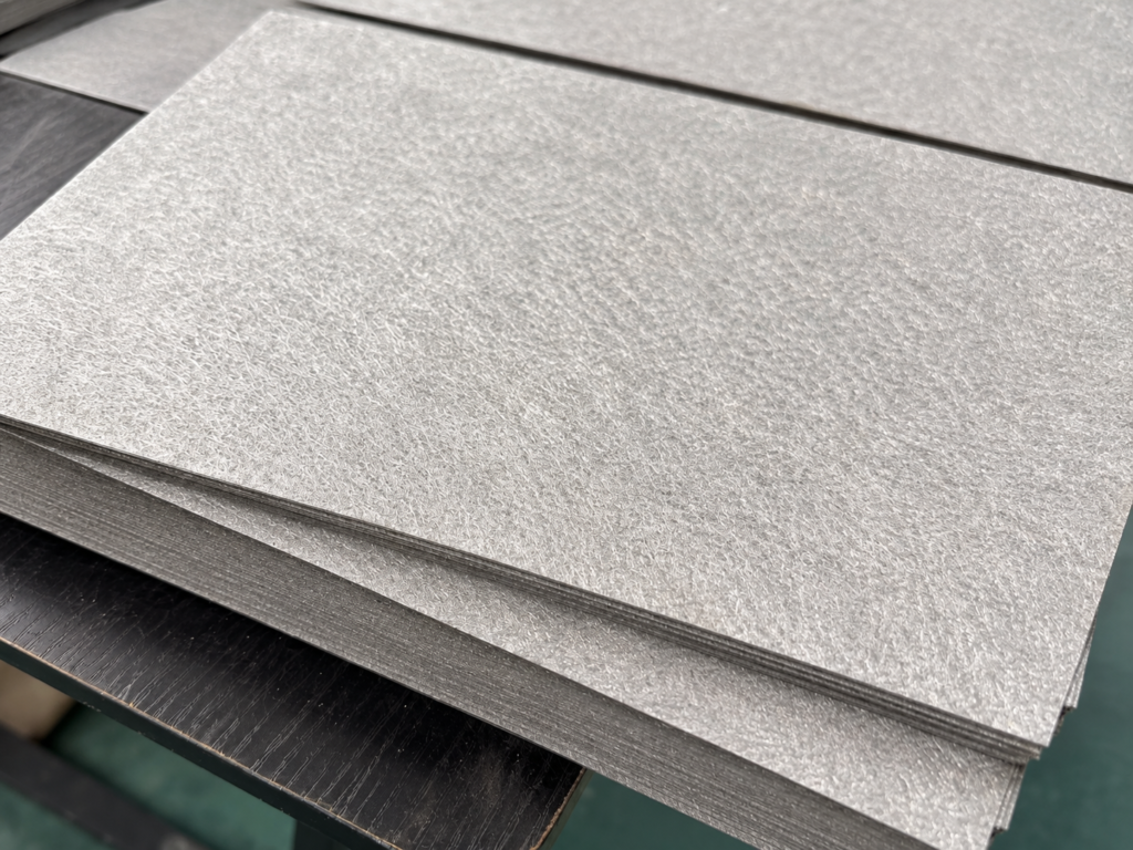
Quick definition: Sintered titanium fiber felt can serve as the anode porous transport layer (PTL) in a PEM water electrolyzer. Its connected pores carry water toward the reaction interface and oxygen away from it, while its fiber network carries electrons and helps support the catalyst layer. Quality therefore involves pore structure, fiber bonding, surface condition, thickness and behavior under compression.
Two batches with the same nominal thickness and porosity can behave differently in an electrolyzer. This guide follows the path from an observed cell problem to the relevant felt variables, manufacturing controls and verification methods. For an introduction to installation position and procurement requirements, see our pure titanium felt PTL selection guide.
By Jack Sun. Our company is based in Anping, Hengshui, Hebei, China, a center of wire mesh manufacturing. Jack Sun has long worked in metal wire mesh weaving and industrial filter-element manufacturing. This article addresses porous-material manufacturing; electrolyzer design and performance require system-level validation.
What Can a Titanium Felt Manufacturer Explain About Cell Performance?
Elevated cell voltage, larger losses at high current density, variation between cells, uneven temperature or declining durability cannot be attributed to titanium felt from those observations alone. The membrane, catalyst layer, coatings, flow field, water supply, temperature, pressure and assembly conditions all contribute.
The felt nevertheless participates in several important pathways. Manufacturing changes that alter pores, fiber junctions, surface peaks or thickness can change transport and contact. The useful question is whether the resulting structure meets the requirements of the intended flow field, compression state and operating conditions—not whether one average porosity is universally suitable.
1. Electrical Losses: Bulk Resistance, Contact and Surface Oxidation
PTL-related electrical resistance includes resistance through the porous material and resistance at its interfaces with neighboring components. The PTL characterization literature distinguishes bulk resistance from interfacial contact resistance; both need appropriate measurement conditions.[1]
Sintered junctions form conducting paths
Before sintering, the felt consists of overlapping fibers. The process develops metallurgical bonds at contact locations. Inadequate bonding can leave a structure susceptible to fiber movement during handling or compression. Excessive sintering can produce shrinkage or local densification that changes the pore network.
A furnace setpoint alone is therefore insufficient as a quality record. Relate the sintering cycle and loading position to finished thickness, porosity, bonding and electrical measurements. An abnormal result should lead to an investigation of the finished structure and process records.
Nominal area is not effective contact area
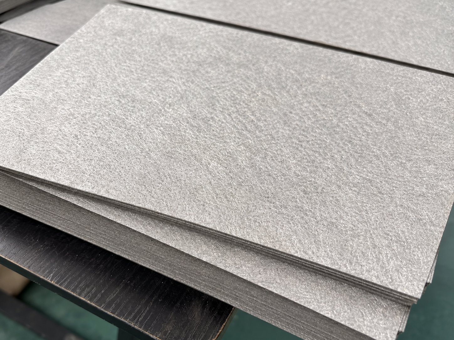
A random fiber surface contains peaks and openings. Two sheets with the same stated thickness may have different height distributions and sparse areas. Under assembly compression, current passes through the contacts actually formed with the catalyst layer and flow field.
Fiber layup, precompression, leveling and sintering shrinkage influence these contacts. Single-point thickness measurements can miss local areas of inadequate compression or high peaks that carry concentrated load.
Corrosion resistance does not guarantee low contact resistance
Titanium passivation can produce a resistive surface oxide. Research examines protective coatings, including platinum- and iridium-based approaches, to manage electrical contact and degradation. Coating chemistry, coverage and durability require validation for the particular anode environment.[3]
This discussion does not mean that every uncoated felt is suitable for direct use, or that a particular coating is part of our standard supply. Specify the required surface condition and qualify it in the intended cell.
2. Water Supply and Oxygen Removal at High Current Density
The anode needs water at the catalyst layer while generated oxygen leaves through the porous structure. Gas occupancy can reduce the space available for liquid transport. Greater oxygen generation at higher current density increases the demands on this two-phase pathway.
Porosity does not describe connectivity
The same total void fraction can occur with different pore sizes, pore throats, connected pathways, tortuosity and local dense regions. Manufacturing control should therefore address the structure through the thickness as well as the average porosity.
Fiber diameter and length establish initial geometric scales. Incomplete dispersion creates fiber bundles; uneven layup changes local solid content; precompression and sintering shrinkage modify the available passages. A restriction can arise locally while a small sample still passes an average-porosity check.
Open transport paths and fine contact structures must work together
A primary study of tape-cast, powder-based titanium PTLs found a tradeoff between contact and gas transport, and investigated pore-former-controlled structures. It provides evidence for considering contact and pore connectivity together, but its fabrication recipe and optimum parameters cannot be transferred directly to fiber felt.[2]
For felt development, a finer interface-facing structure and a more open backing layer are possible design directions. Their coverage, thickness and connection must be controlled so the finer region does not become a transport restriction.
Thickness is part of the assembly design
Thickness affects through-plane transport distance and electrical and mechanical paths. A thinner sheet is not automatically a better PTL: the result also depends on water distribution, flow-field lands and channels, gasket geometry and compression. The manufacturer’s role is to reproduce the agreed thickness and structure consistently, rather than select a universal optimum for every cell.
3. Uniformity Across the Sheet and Production Batch
Spatial differences in thickness, pore structure or contact can contribute to different local transport and electrical conditions. A satisfactory average can conceal variation between the center and edges, along the production direction or between furnace positions.
Fiber dispersion and controlled layup
Undispersed bundles create concentrated solid regions next to sparse regions. Control mass per unit area and the arrangement and overlap of successive layers. Later leveling can adjust thickness, but cannot fully remove a nonuniform distribution of solid material established during layup.
Measure across the usable area
For larger active areas and repeated production, map thickness, mass per unit area and relevant permeability measurements across longitudinal, transverse and edge locations. A small central specimen should not be treated as proof that the entire sheet or batch meets the same requirements.
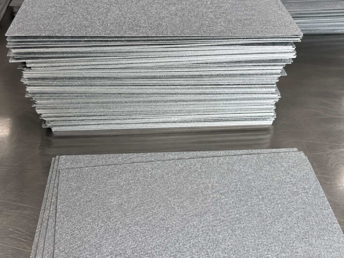
Use the measurement map and batch statistics to distinguish random variation from equipment directionality, position-dependent shrinkage and differences between furnace runs.
4. Surface Morphology and Mechanical Contact
Compression helps establish electrical contact, but the load is carried at actual contact locations. Protruding fibers, large pore edges and regions beneath flow-field lands can experience different conditions. Assess local contact and the condition of neighboring thin layers together with the assembly compression.
Control surface peaks as well as average thickness
Insufficient precompression can leave high surface features or unstable thickness. Excessive compression can narrow passages or create dense regions. Check thickness distribution, surface profile and the change after compression instead of judging a sheet only by visual smoothness.
Inspect cut edges and loose fibers
Raised edge fibers, burrs and loose particles can create unwanted contact with adjacent layers during assembly. Suitable cutting, edge inspection, cleaning and clean packaging should form part of the acceptance plan. Dimensional conformity alone does not cover these conditions.
5. Sintered Bonds and Structural Stability
The PTL must retain the required structure under assembly loading and operating conditions. A poorly bonded network may rearrange unpredictably when compressed; a highly densified network may retain its outline while losing useful transport passages.
Temperature, dwell time, heating and cooling rates, atmosphere or vacuum, furnace loading and support fixtures can influence bonding, shrinkage and warping. A successful sintering condition reported for powder-based PTLs is not a universal furnace prescription for titanium fiber felt.
Why consider mesh reinforcement?
Where a felt alone cannot meet both interface and structural requirements, a titanium mesh backing can provide additional support and current collection while the felt provides the interface-facing porous region. This is a design option, not an automatic improvement. Bond quality, thickness, parallelism and shrinkage must be assessed after joining.
6. Surface Treatment, Coating Coverage and Cleanliness
Low initial resistance does not establish stable resistance over time. Surface oxidation, coating defects and changes at the catalyst-layer interface can influence later behavior. Evaluate the surface treatment with an appropriate durability test.
A fiber network is harder to coat than a flat plate
Fiber intersections, pore openings and sheltered regions complicate uniform coverage. The same average coating loading does not prove that every exposed region has the intended coverage. Link cleaning, surface preparation, fixture orientation and deposition method to actual coverage and electrical measurements.
Reported coating thickness or an equipment setting alone cannot describe its distribution throughout a rough porous surface. Surface and cross-sectional examination can help evaluate the regions relevant to the design.
Keep contamination control continuous
Fiber preparation, layup, cutting, leveling and handling can introduce oil, particles, abrasives or packaging residues. At a closely contacting electrochemical interface, residues may affect local contact or subsequent surface treatment. Any claim of metal-ion release or membrane contamination requires appropriate analysis.
Cleaning medium, rinsing, drying, handling and packaging should form a continuous process. Cleaning is part of interface preparation rather than only a final appearance check.
7. Tracing Cell Problems to Manufacturing Controls
| Problem to investigate | Relevant felt variables | Manufacturing records | Verification |
|---|---|---|---|
| Ohmic loss or resistance growth | Fiber junctions, contact, oxidation and coating coverage | Sintering, leveling, cleaning and surface treatment | Bulk and contact resistance under defined conditions; aging response |
| High-current transport loss | Pore throats, connectivity, tortuosity and thickness | Fiber selection, dispersion, layup, precompression and shrinkage | Pore structure, permeability and cell-level transport analysis |
| Local or cell-to-cell variation | Spatial thickness, areal mass and pore distribution | Layup, equipment direction, furnace position and leveling | Measurement maps, batch statistics and cell comparison |
| Unwanted local mechanical loading | Surface peaks, large openings, loose fibers and compression response | Surface-layer layup, leveling, cutting and cleaning | Surface profiles, compression curves and post-compression inspection |
| Structural change under loading | Bond strength, recovery and interlayer connections | Sintering cycle, layer arrangement, fixtures and finishing | Compression cycles, bond integrity and retained geometry |
| Progressive degradation | Oxidation, coating defects and residues | Surface preparation, deposition, cleaning, drying and packaging | Coverage, interface resistance and durability tests |
This table gives investigation paths rather than diagnoses. First separate the cell’s ohmic, transport and kinetic contributions. Then test whether the felt’s structure or interface is consistent with the observed behavior before attributing the problem to manufacturing.
8. Two Approaches to Composite PTL Structures
A composite can assign transport, interface contact and mechanical support to different regions. Each added layer also introduces bonding, shrinkage, thickness and flatness requirements. Comparative tests are needed to establish an advantage in the intended assembly.
Titanium mesh and felt joined into one component
One approach combines a mesh support with a titanium fiber felt layer. Joining should create the intended stable bonds at their contacts. Inspect interlayer integrity, shrinkage-induced warping, mesh imprinting, total thickness, local filling and edge condition after cutting.
A joined component may reduce the number of separate assembly interfaces. It does not by itself prove lower contact resistance or more reliable sealing. The finished geometry and compressed contact state need verification.
Felt with a finer microporous surface layer
Another approach introduces a finer titanium microporous layer near the catalyst-facing interface while retaining a more open bulk transport structure. The layer is intended to manage contact and local transport; its actual effect depends on thickness, porosity, coverage and bonding.
Check thickness uniformity, continuity, cracks, delamination, agglomeration and possible obstruction of backing-layer pores. A layer that is too restrictive may increase transport losses; incomplete coverage or weak bonding can produce inconsistent interface behavior.
Composite thicknesses, porosity targets and microporous-layer dimensions are design-specific. Example values in a development proposal are not universal PEM design recommendations or qualified performance guarantees.
9. How to Verify a Manufacturing Improvement
Choose verification methods that address the intended improvement. For electrical losses, define compression and contact materials before measuring bulk and interface resistance. For transport, combine pore and permeability measurements with cell testing at relevant current density. For mechanical concerns, inspect thickness, surface features and contact condition before and after compression.
Different measurements answer different questions. Flow porometry evaluates connected flow passages within its method limits; microscopy and tomography examine spatial structure; thickness and profile measurements describe assembly geometry; electrical testing evaluates conducting paths. Polarization and impedance measurements then bring the component back into cell conditions.
Use samples from the same identified batch for manufacturing and electrochemical measurements. Laboratory specimens can demonstrate potential; repeat production must also show that sheet locations, furnace runs and successive batches remain within the agreed limits.
10. Frequently Asked Questions
Why can transport losses occur when porosity meets specification?
Porosity does not fully describe pore throats, connectivity, tortuosity or local dense regions. A few restrictive pathways can affect transport while an average measurement remains acceptable.
Does higher sintering temperature always improve titanium felt?
No. Stronger junctions can be accompanied by greater shrinkage or densification. Verify bonding together with thickness, pores and electrical response under the applicable process conditions.
Does a smoother surface always give better catalyst-layer contact?
Lower peaks can improve the contact distribution, but excessive densification may restrict transport. Evaluate actual compressed contact, resistance and permeability rather than appearance alone.
Can a microporous layer solve both contact and transport problems?
It is one design option. The result depends on its pores, thickness, coverage and connection to the felt. A restrictive or nonuniform layer can introduce new problems.
Can a felt manufacturer guarantee electrolyzer efficiency and life?
Material acceptance can cover agreed composition, dimensions, structure, surface condition and batch consistency. Cell efficiency and life also depend on the membrane electrode assembly, coatings, flow field, water, temperature, pressure and controls. These require system-level testing.
Connecting Process Records with Performance Evidence
Sintered titanium felt quality influences transport through its pore network, electrical paths through fiber junctions and interfaces, and mechanical contact through its thickness and surface profile. Fiber selection, layup, precompression, sintering, cutting, cleaning and surface treatment therefore need to be considered as a connected process.
A useful manufacturing improvement links an identified cell problem to measurable structural variables, repeatable production controls and tests under relevant conditions. Contact our engineers with the flow-field design, active area, operating current density, compression requirements, surface-treatment specification and observed problem to discuss material and sample requirements.
Technical References
- Stelmacovich and Pylypenko, Characterization of Porous Transport Layers Towards the Development of Efficient Proton Exchange Membrane Water Electrolysis, ChemElectroChem, 2024. Background on characterization and interface requirements.
- Lee and colleagues, Titanium porous-transport layers for PEM water electrolysis prepared by tape casting. Powder-based primary research; its recipe is not a fiber-felt manufacturing specification.
- Degradation of PGM and PGM-free Coatings on PEMWE Porous Transport Layers, ACS Applied Materials & Interfaces, 2025, DOI 10.1021/acsami.4c22455. Comparative research on coating degradation.