
By Jack Sun · Updated October 23, 2026
Quick definition
Measuring a replacement metal filter cartridge means recording dimensions, connections, seal locations, supports and installation direction. Outside diameter, inside diameter and total length establish only an initial outline. A part that fits is not automatically equivalent in sealing, pressure-drop behavior or filtration performance.
This guide and its grouped worksheet mainly describe cylindrical cartridges, including pleated, sintered and formed wire-mesh elements. Keep known model data, drawings, measurements and unknown items distinct. The diagrams are conceptual measuring references, without manufacturing dimensions or tolerances.
Other element shapes need their own datums: use pressure filter leaf information for planar leaves and their outlets, strainer information for baskets and temporary elements, and SPL/DPL element information for stacked discs. The same cylindrical diameter/length fields do not fully describe those assemblies.
Start with the drawing, existing specification or sample information you already have. Use the worksheet to clarify missing manufacturing or inspection details; it is not a requirement to complete every field before contacting us.
1. Collect the existing information
Save equipment model, full cartridge part number and suffixes, drawing revision, maintenance instructions and data sheets. Photograph markings and transcribe them. Record installation position and quantity where similar versions exist.
Measure a sample already removed and made safe to handle according to the equipment and site procedures. This guide does not replace dismantling, depressurization or residual-fluid handling instructions. Record whether the sample is new, used, cleaned or damaged.
Wear, deposits, deformation and compressed seals can alter old dimensions. Preserve original readings and observations instead of rounding them into assumed standard sizes. Use explicit units, generally mm, while keeping original inch data and their source where applicable. Unit conversion does not add measurement precision or change tolerances.
2. Filter cartridge diameter and length
Outside diameter
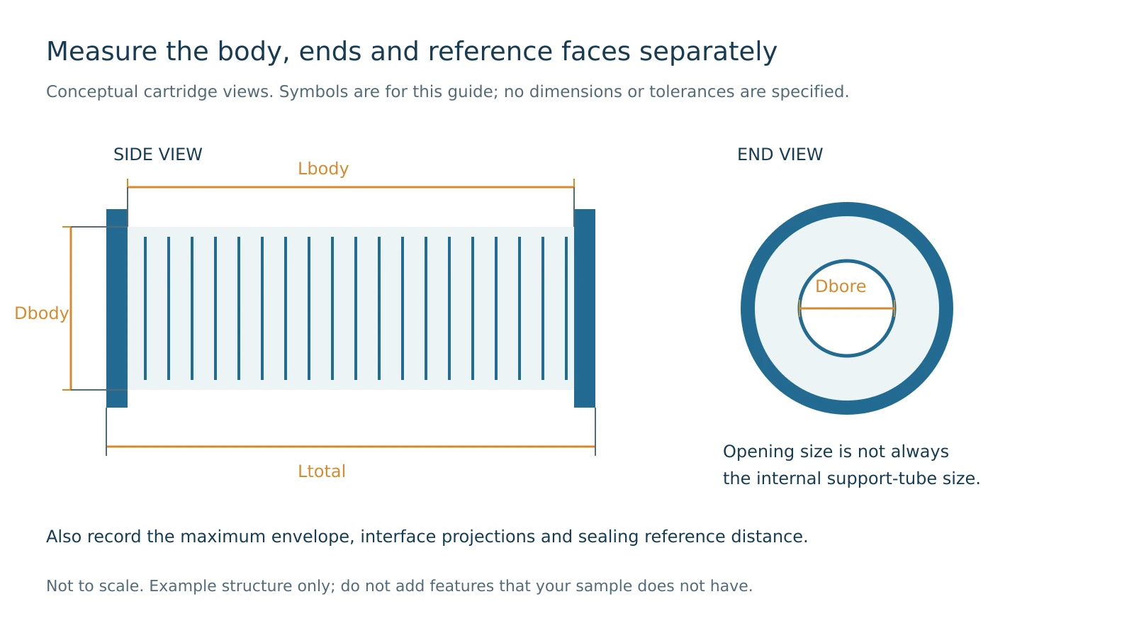
Separate body, end-cap, protective-sleeve, reinforcement and connection diameters. Record the maximum envelope and the feature causing it. Measure near both ends and the middle where appropriate, with directions identified; avoid deforming thin sleeves or pleats with measuring force.
Inside diameter
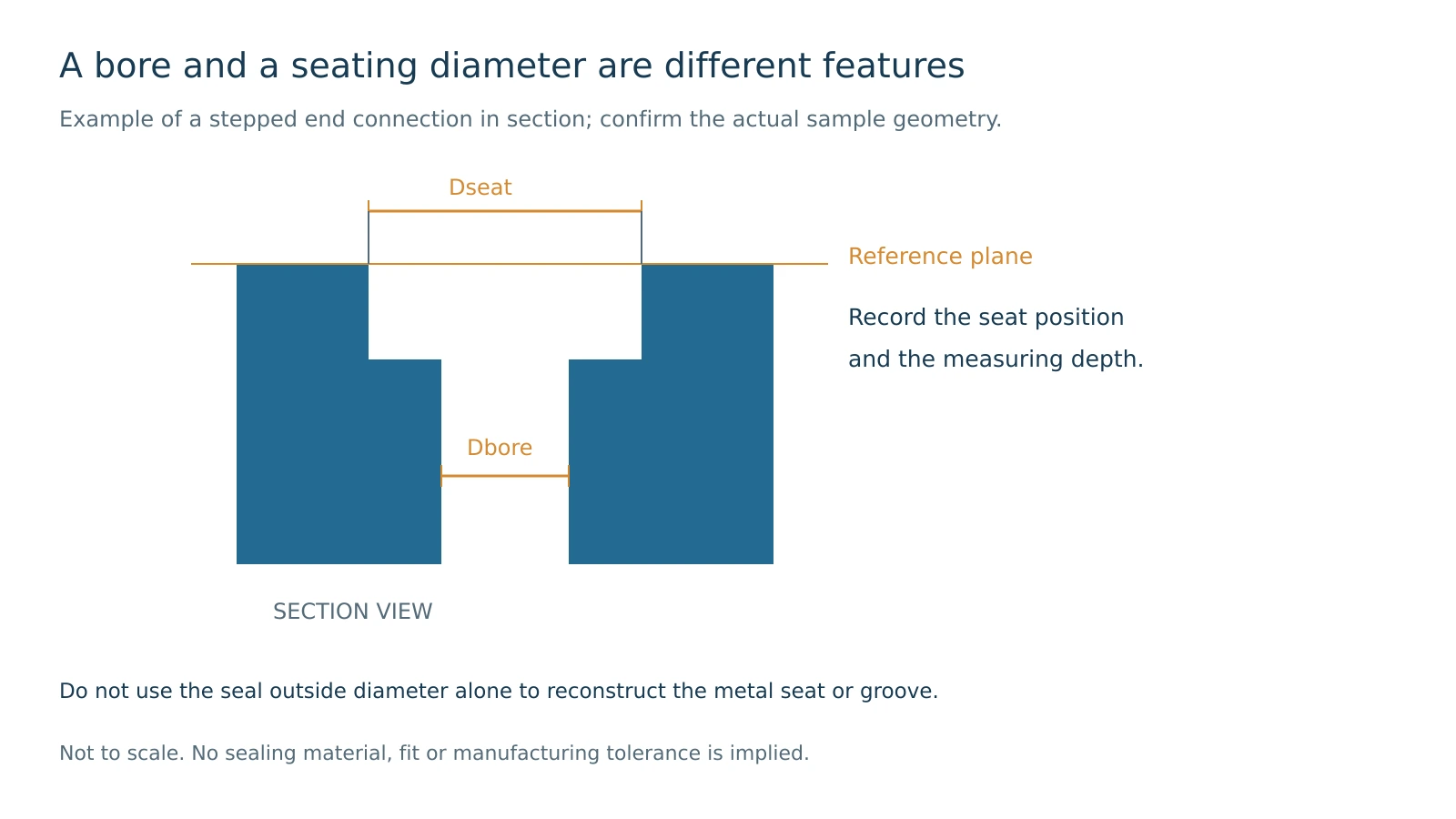
Distinguish the end opening, internal support bore and seating or sealing step. State the end and measurement depth. A caliper reading at an unidentified depth is not a complete through-bore specification. Deep or stepped features may require suitable gauges, drawings or sample review.
Length and datums
Total length, filtering body length and distance between seating/sealing datums differ. Identify whether threads, studs, handles, adapters or gaskets are included. Keep free seal dimensions separate from installed compressed conditions.
| Symbol used here | Measurement | Boundary to identify |
|---|---|---|
| Dbody | Filter body outside diameter | Body only; exclude projecting features |
| Dmax | Maximum external envelope | Include projections and name the feature |
| Dbore | End opening/bore | End and measuring depth |
| Dseat | Seating/sealing diameter | Specific step or mating surface |
| Ltotal | Overall length | Datums and included components |
| Lbody | Filtering body length | Agreed start/end points |
| Lseat | Seating/sealing datum distance | Datums and seal state |
These symbols are editorial conventions, not universal industry notation. Use the actual drawing’s definitions. Mark absent features “not applicable.”
3. Connections
Threads
Record internal/external, straight/tapered, visible engagement length, pitch or threads per inch, and the complete known designation. Diameter alone cannot reliably distinguish metric, imperial and pipe-thread series.
G, R, Rp, Rc and NPT are not interchangeable names. ISO 228-1 addresses pipe threads where pressure-tight joints are not made on the threads; ISO 7-1 covers pressure-tight thread joints; ASME B1.20.1 covers general-purpose inch pipe threads including NPT. [1][2][3] Confirm with the correct designation and suitable gauges. Nominal pipe-thread size is not a measured outside diameter.
If only preliminary measurements exist, write “suspected thread, to be confirmed” instead of ordering against an unverified label.
Inserted or stepped connections
Record insertion diameter/length, steps, stops and seal positions. For multiple O-ring grooves, identify each groove’s width, depth or root diameter, spacing and distance from the end. A worn or swollen O-ring outside diameter alone cannot recover the metal mating geometry.
Flanges and special locating features
Record flange diameter, thickness, bore, bolt-hole count/diameter, positions or bolt circle, sealing face and steps. Diameter and hole count alone do not establish a flange standard. Record bayonets, tabs, rods, locking rings and eccentric features individually. Complex shapes need datum-based drawings or sample review.
4. Seals and locating surfaces
Identify face gasket, radial O-ring, cone, thread joint or another sealing interface. Threads may provide retention while a separate face provides the seal. [1]
Record seal count, position, free dimensions and known material. Color or feel does not reliably establish NBR, FKM or EPDM. Include fluid, temperature and cleaning conditions for compatibility review.
Photograph metal mating surfaces and record scratches, wear, corrosion and scale before any modification. An old sample does not establish original tolerances; successful insertion into one old housing does not alone establish suitable seal compression or batch limits.
5. Flow direction, supports and media
Confirm outside-in, inside-out or another flow path from equipment drawings, instructions or markings. A dirty face or visible support tube is only a clue.
Distinguish internal support, outer sleeve, reinforcing rings and filtering layers. A perforated sleeve can surround woven mesh, sintered mesh or metal fiber felt; sleeve holes do not define the filter rating. See our pleated metal filter information.
Record bypass, check-valve and spring functions and whether they belong to the element or housing. Matching an empty cylinder’s envelope does not reproduce a functional assembly.
Keep performance requirements separate: grade definition, efficiency method, flow, temperature, viscosity, system pressure and allowable element differential pressure. System pressure is not element differential pressure. Equal dimensions do not establish equal area or flow/pressure behavior.
A change in medium or grade is a design change requiring agreed validation, rather than an already-proven equivalent replacement. Read the filter micron rating and efficiency guide.
Identifying a sintered mesh replacement
For a sintered mesh cartridge, retain any known layup or material-table model, laminate thickness, filtration-layer position and marked inlet face. Keep an outer protective mesh or a perforated support separate from the actual laminate specification. Surface appearance and equal outside dimensions do not identify an equivalent construction.
Record active filtering length and any area occupied by seams, sealed edges or support contacts. Confirm normal flow and any reverse cleaning against the inner and outer supports. For a flow comparison, keep fluid, temperature, flow rate and pressure-measurement boundary with the original curve or result.
Begin with the existing drawing, specification or sample information. If it already defines the construction, use it directly; clarify only missing items affecting manufacture or acceptance. Unknown original layer or performance details remain open for review. See sintered mesh layers, support and flow direction and our sintered mesh supply forms and inspection scope.
6. Photographs and filter element measurement records
Prepare an overall side view, both ends, connection side views, seal close-ups, media/support detail and critical measurement photographs. Match each to sample number and measuring-point symbols.
Show both instrument reading and contact location. Record units, state and method in text. Perspective photographs should not be used to infer precision dimensions. Instrument resolution, calibration, contact conditions and uncertainty matter; displayed digits alone do not establish accuracy. [4]
Retain readings at each point and identify damaged areas. Keep unknown original dimensions or tolerances unresolved until review. Batch manufacture requires agreed drawings and acceptance requirements.
7. Custom filter cartridge preparation routes
Custom to requirements: provide process fluid, contaminants, grade, flow, temperature, pressure drop and space constraints to discuss structure and validation.
Custom to drawing: provide the complete revision, material, dimensions, tolerances, connection and acceptance requirements, including any differences from the old sample.
Sample-based review: recover measurable dimensions and observable construction; verify material and filtration performance separately. Agree on sample condition and handling before shipment.
The grouped recording checklist below can be copied or printed. Use values, “unknown,” or “not applicable,” and keep a source for each item. It is a local worksheet, not an online submission form.
Identification
| Field | Value and unit | Source / status / note |
|---|---|---|
| Sample ID | __________ | __________ |
| Original brand and full part number | __________ | __________ |
| Equipment model and installation position | __________ | __________ |
| Quantity | __________ | __________ |
| Drawing number and revision | __________ | __________ |
| Sample state: new / used / cleaned / damaged | __________ | __________ |
| Measurement date and person | __________ | __________ |
| Dimension units | __________ | __________ |
Dimensions
| Field | Value and unit | Source / status / note |
|---|---|---|
| Dbody: locations, directions and individual readings | __________ | __________ |
| Dmax: feature and readings | __________ | __________ |
| Dbore: end and measuring depth | __________ | __________ |
| Dseat: measuring location | __________ | __________ |
| Ltotal: datums and included parts | __________ | __________ |
| Lbody: start and end points | __________ | __________ |
| Lseat: datums and seal state | __________ | __________ |
Connections and seals
| Field | Value and unit | Source / status / note |
|---|---|---|
| Connection type | __________ | __________ |
| Thread: internal/external, straight/taper and full designation | __________ | __________ |
| Pitch or threads per inch; source and certainty | __________ | __________ |
| Insertion dimensions and stop | __________ | __________ |
| Seal groove dimensions and locations | __________ | __________ |
| Flange, holes, positions and sealing face | __________ | __________ |
| Seals: count, free dimensions and known material | __________ | __________ |
Media and operating conditions
| Field | Value and unit | Source / status / note |
|---|---|---|
| Known medium and supports | __________ | __________ |
| Powder body: active porous length and wall thickness; dense end/connection zones; seal details; original flow result and rating definition, if known | __________ | __________ |
| Compressed knitted body: net mesh mass excluding separate inserts; central holes/insert boundaries; free and loaded heights with measuring force; deposits or permanent set | __________ | __________ |
| Perforated support: hole pattern and direction; wall thickness; weld band and blank ends; shape/roundness; side contacting the fine medium; observed service deformation | __________ | __________ |
| Etched sheet: solid borders, hole-pattern direction, weld lands and mounting face; flat or formed state; both-face/edge photographs and damaged regions | __________ | __________ |
| Nominal/absolute grade and definition | __________ | __________ |
| Efficiency requirement and method | __________ | __________ |
| Normal flow direction and evidence | __________ | __________ |
| Reverse-cleaning requirements | __________ | __________ |
| Bypass, check valve and springs; locations | __________ | __________ |
| Fluid, contaminant, temperature and viscosity | __________ | __________ |
| Flow and units | __________ | __________ |
| System pressure and units | __________ | __________ |
| Permitted element differential pressure and units | __________ | __________ |
| Clean and terminal pressure-drop conditions | __________ | __________ |
| Known material and documentation | __________ | __________ |
Measurement and evidence
| Field | Value and unit | Source / status / note |
|---|---|---|
| Instrument, ID, calibration and resolution | __________ | __________ |
| Contact state and method | __________ | __________ |
| Dimension/tolerance source: drawing, standard or agreement | __________ | __________ |
| Wear, deformation, corrosion and deposits | __________ | __________ |
| Photo IDs and corresponding points | __________ | __________ |
| Unknown and unresolved items | __________ | __________ |
| Manufacturing route: requirements / drawing / sample | __________ | __________ |
| Attachments | __________ | __________ |
8. Frequently asked questions
Are outside diameter, inside diameter and total length enough?
They establish an outline; connection, seal, locating, material, flow and performance still need confirmation.
Can an old cartridge length define a new tolerance?
No. Use the drawing, agreed standard or confirmed requirement.
Does thread outside diameter identify the thread?
Pitch, straight/taper form, series and proper mating verification are also needed.
Is sleeve hole size the filtration rating?
Support and filtering medium have different functions.
What if I have only a sample?
Supply photographs, measurements and operating data, preserving unknowns for sample review.
Does the same shape guarantee the same filtration?
Structure, area, seals, flow and test conditions can differ.
Can O-ring color identify its material?
Use original specifications or suitable material information.
Must the cartridge be cut open?
Initial recording does not require destruction. Agree on any later dismantling or section inspection after preserving complete records.
References
- ISO 228-1:2000 — Pipe threads.
- ISO 7-1:1994 — Pressure-tight pipe-thread joints.
- ASME B1.20.1 — General-purpose inch pipe threads.
- NIST — Uncertainty and dimensional calibrations.
Related guides
Metal mesh identification · Wire mesh terminology
About the author: Jack Sun has long experience in wire weaving and industrial filter manufacturing. Our company is based in Anping, Hengshui, Hebei, China. Project manufacture and acceptance follow the confirmed drawing, operating conditions and agreed requirements.