
By Jack Sun · Updated October 12, 2026
Quick definition
Wire gauge identifies a nominal wire size through a numbered system. AWG, SWG and BWG use different diameter tables. The same number can mean different diameters; specify the system and the wire diameter in mm with its agreed tolerance.
This wire gauge chart covers gauges 8–36 for wire mesh and filter manufacturing discussions. It does not provide electrical ampacity, insulation diameters or sheet-metal gauge sizes.
1. AWG, SWG and BWG
AWG (American Wire Gauge) has a geometric progression. ASTM B258 addresses standard nominal diameters and areas of solid round electrical-conductor wire. Its public scope does not establish electrical performance for arbitrary mesh wire. [1]
SWG (British Standard Wire Gauge) has its own discrete diameter table. Its historical name does not establish that every British purchase uses SWG or that every historical document is a current acceptance standard.
BWG (Birmingham Wire Gauge) is separate from British Standard Wire Gauge; NBS Circular 67 lists the systems separately. [3] BWG can also appear in tube-wall references: that does not make the gauge value the tube outside diameter.
Within the 8–36 range here, increasing gauge numbers mean decreasing diameter. This is not a rule for every system called gauge, nor a constant mm decrement per number.
2. AWG vs SWG and SWG vs BWG: diameter table
AWG uses nominal inch values from NBS Handbook 100 Table 1, SWG its British standard table (Table 15), and BWG the Birmingham column in NBS Circular 67. Inch values are multiplied by exactly 25.4 and displayed to four decimal places. [2][3][4]
These are historical nominal references and independent unit conversions. Four decimal places do not establish ±0.0001 mm tolerance. This is not a reproduction of the current ASTM B258 full table or a compliance declaration. Acceptance uses the contract’s specified standard, drawing and tolerance.
| Gauge | AWG nominal mm | SWG nominal mm | BWG nominal mm |
|---|---|---|---|
| 8 | 3.2639 | 4.0640 | 4.1910 |
| 9 | 2.9058 | 3.6576 | 3.7592 |
| 10 | 2.5883 | 3.2512 | 3.4036 |
| 11 | 2.3038 | 2.9464 | 3.0480 |
| 12 | 2.0523 | 2.6416 | 2.7686 |
| 13 | 1.8288 | 2.3368 | 2.4130 |
| 14 | 1.6281 | 2.0320 | 2.1082 |
| 15 | 1.4503 | 1.8288 | 1.8288 |
| 16 | 1.2903 | 1.6256 | 1.6510 |
| 17 | 1.1506 | 1.4224 | 1.4732 |
| 18 | 1.0236 | 1.2192 | 1.2446 |
| 19 | 0.9119 | 1.0160 | 1.0668 |
| 20 | 0.8128 | 0.9144 | 0.8890 |
| 21 | 0.7239 | 0.8128 | 0.8128 |
| 22 | 0.6426 | 0.7112 | 0.7112 |
| 23 | 0.5740 | 0.6096 | 0.6350 |
| 24 | 0.5105 | 0.5588 | 0.5588 |
| 25 | 0.4547 | 0.5080 | 0.5080 |
| 26 | 0.4039 | 0.4572 | 0.4572 |
| 27 | 0.3607 | 0.4166 | 0.4064 |
| 28 | 0.3200 | 0.3759 | 0.3556 |
| 29 | 0.2870 | 0.3454 | 0.3302 |
| 30 | 0.2540 | 0.3150 | 0.3048 |
| 31 | 0.2261 | 0.2946 | 0.2540 |
| 32 | 0.2032 | 0.2743 | 0.2286 |
| 33 | 0.1803 | 0.2540 | 0.2032 |
| 34 | 0.1600 | 0.2337 | 0.1778 |
| 35 | 0.1422 | 0.2134 | 0.1270 |
| 36 | 0.1270 | 0.1930 | 0.1016 |
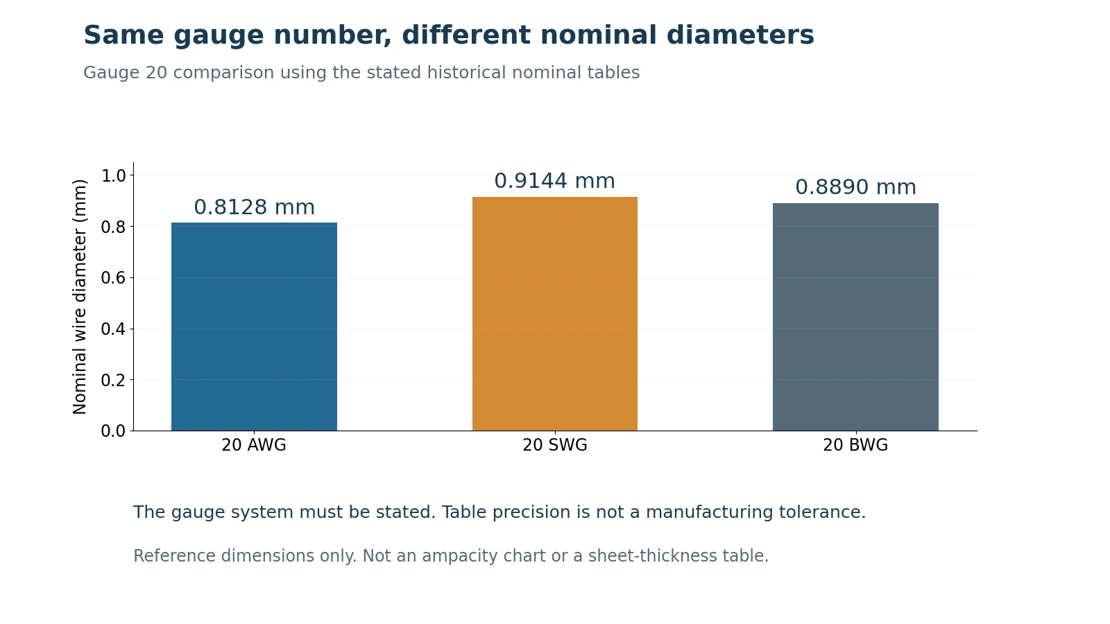
For gauge 20, this table gives AWG 0.8128 mm, SWG 0.9144 mm and BWG 0.8890 mm. A drawing marked only “20 gauge” needs clarification. Do not infer the system from geography or alloy.
A measured 0.90 mm wire is not automatically 20 SWG or 20 BWG. Discuss substitution against actual specifications and tolerances. This selected range omits zero-gauge series and other sizes; an omitted row does not mean the size does not exist. Never interpolate SWG or BWG from adjacent rows.
3. AWG formula vs nominal table values
The ideal progression is:
d(in) = 0.005 × 92^((36 − n)/39)
d(mm) = 0.127 × 92^((36 − n)/39)
Here n is the AWG number. For 20 AWG, the formula gives approximately 0.811821 mm, while the historical nominal 0.0320 in converts to 0.8128 mm. The approximately 0.000979 mm difference arises from the selected nominal rounding basis, not another gauge system.
If a table shows 0.812 mm, check whether it uses an ideal formula, rounded nominal inches or a specified standard table. Keep calculation precision separate from manufacturing tolerance. SWG and BWG do not use the AWG formula.
4. AWG to mm, SWG to mm and BWG to mm
First obtain the diameter in the correct system. Multiply inches by 25.4 for mm; divide mm by 25.4 for inches. 1 mil = 0.001 in = 0.0254 mm. [4] Thus 32 mil is 0.032 in or 0.8128 mm, not 32 mm or 0.032 mm.
Diameter uses mm; area uses mm². For a solid circular section, A = πd²/4. A 1.00 mm diameter gives approximately 0.7854 mm². It is not a 1 mm² wire. For an equivalent solid circle, d = √(4A/π).
Flat wire needs width and thickness; profile wire needs its section; stranded conductors need strand diameter, count and construction. Insulated wire requires distinguishing conductor and insulation diameters. These geometric relationships do not provide electrical design ratings.
5. Wire gauge vs mesh count
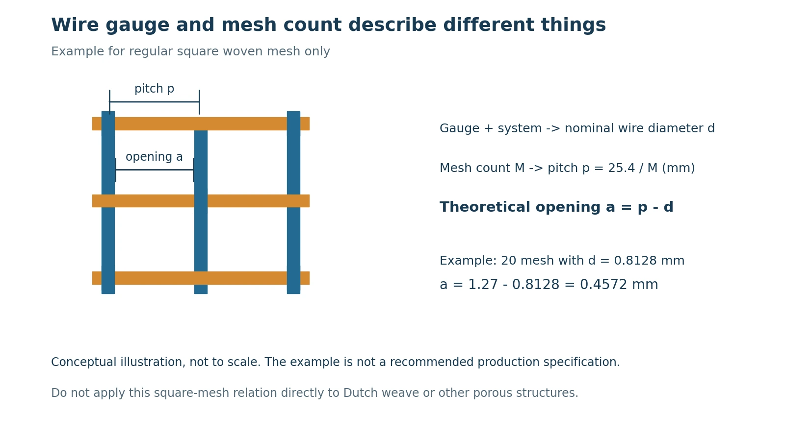
Wire gauge describes wire size. Mesh count describes directional grid repetition under its stated convention. “20 gauge” and “20 mesh” are different parameters.
For applicable regular square woven mesh, theoretical clear aperture in mm is a = 25.4/M − d, where M is mesh count per inch and d is wire diameter in mm.
A teaching example at 20 mesh has pitch 1.27 mm. Using the gauge-20 values above gives apertures of 0.4572 mm (AWG), 0.3556 mm (SWG) and 0.3810 mm (BWG). These demonstrate the effect of missing the system; they are not recommended factory specifications.
This square-opening relationship does not directly apply to Dutch weave, knitted mesh, wedge wire or sintered powder. Aperture does not establish removal efficiency.
Use the wire mesh size calculator with explicit geometry. Specify material, weave, warp/weft counts, warp/weft diameters, dimensions and tolerances; distinguish bare from coated wire.
6. Measuring and specifying wire diameter
Identify bare wire, coated diameter, individual strand or bundle. Choose resolution, calibration and contact force for the measurement target. Displayed decimal places alone do not establish accuracy.
Measure multiple positions and, where appropriate, directions to assess variation or ovality. Avoid damaged crossings, burrs and bends as representative locations. Wire removed from woven material may be deformed; record the sampling method.
Record material grade; original gauge system/number if known; nominal diameter in mm; tolerance and source; measurement state; warp/weft construction; finished dimensions and processing; and acceptance method/version. Preserve a real mm specification instead of forcing an approximate gauge label.
7. Frequently asked questions
Are 20 AWG, 20 SWG and 20 BWG the same?
No. This reference gives 0.8128, 0.9144 and 0.8890 mm respectively. ### Does a larger gauge number mean thicker wire? In the range covered here, diameter decreases as number increases. Check other systems separately. ### Is 0.90 mm automatically 20 SWG? No. Compare the specification and permissible tolerance. ### What if the AWG formula differs from a table? Check nominal rounding and use the contract’s specified table and tolerance. ### Can the AWG formula calculate SWG? No; use the SWG or BWG discrete table. ### Can gauge replace mesh count? No. Both diameter and directional mesh data are needed. ### Is insulated wire outside diameter the AWG diameter? Distinguish conductor construction and insulation; this chart does not provide ampacity. ### Can this table be used for 20 gauge sheet metal? Use the material-specific sheet-thickness system or an explicit mm thickness instead.
Sources
- ASTM B258 — Standard nominal AWG diameters and areas. Scope reference, not a current-table compliance claim.
- NBS Handbook 100 — Copper Wire Tables, 1966. Tables 1 and 15 provide selected historical nominal inch values.
- NBS Circular 67 — Wire Gages, 1918. Historical BWG reference and system distinction.
- NIST Engineering Metrology Toolbox. Exact international inch conversion.
Related guides
Metal mesh identification · Filter rating and efficiency · Wire mesh glossary
About the author: Jack Sun has long experience in wire weaving and industrial filter manufacturing. Our company is based in Anping, Hengshui, Hebei, China. Project manufacture and acceptance follow the confirmed drawing, operating conditions and agreed requirements.