Quick Definition
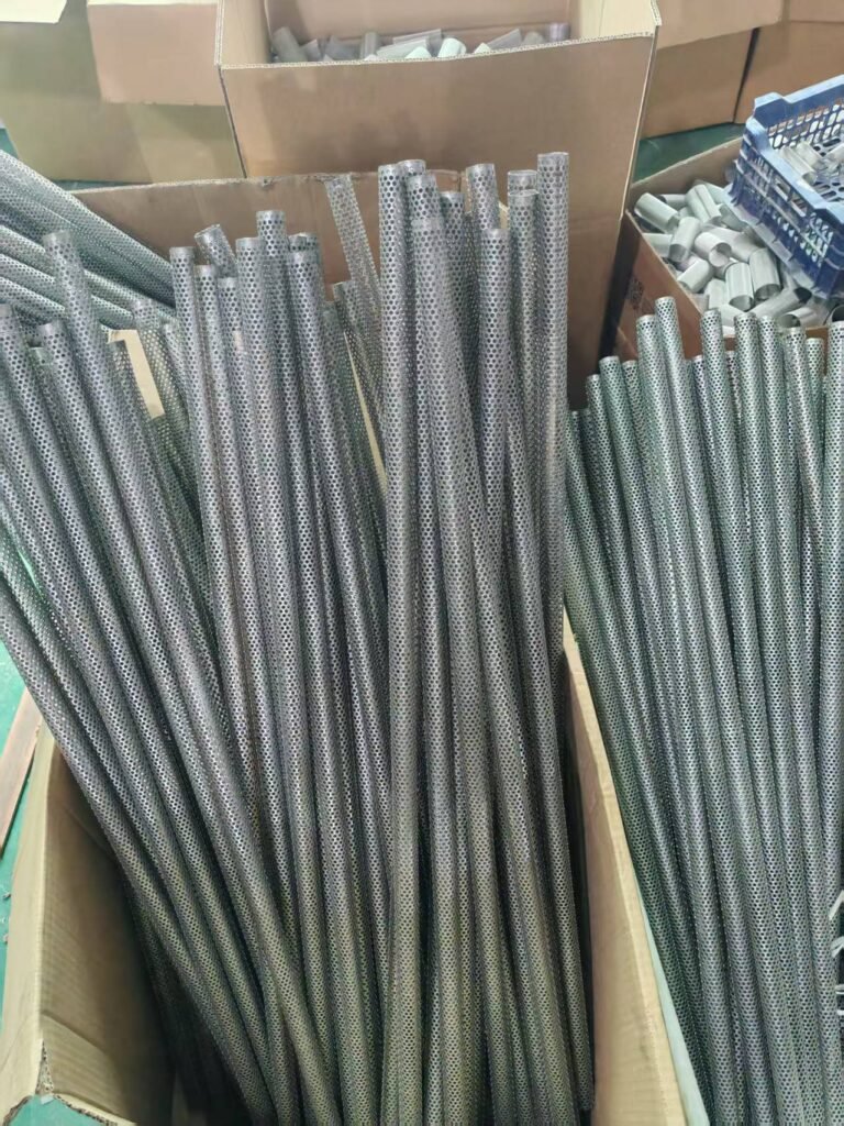
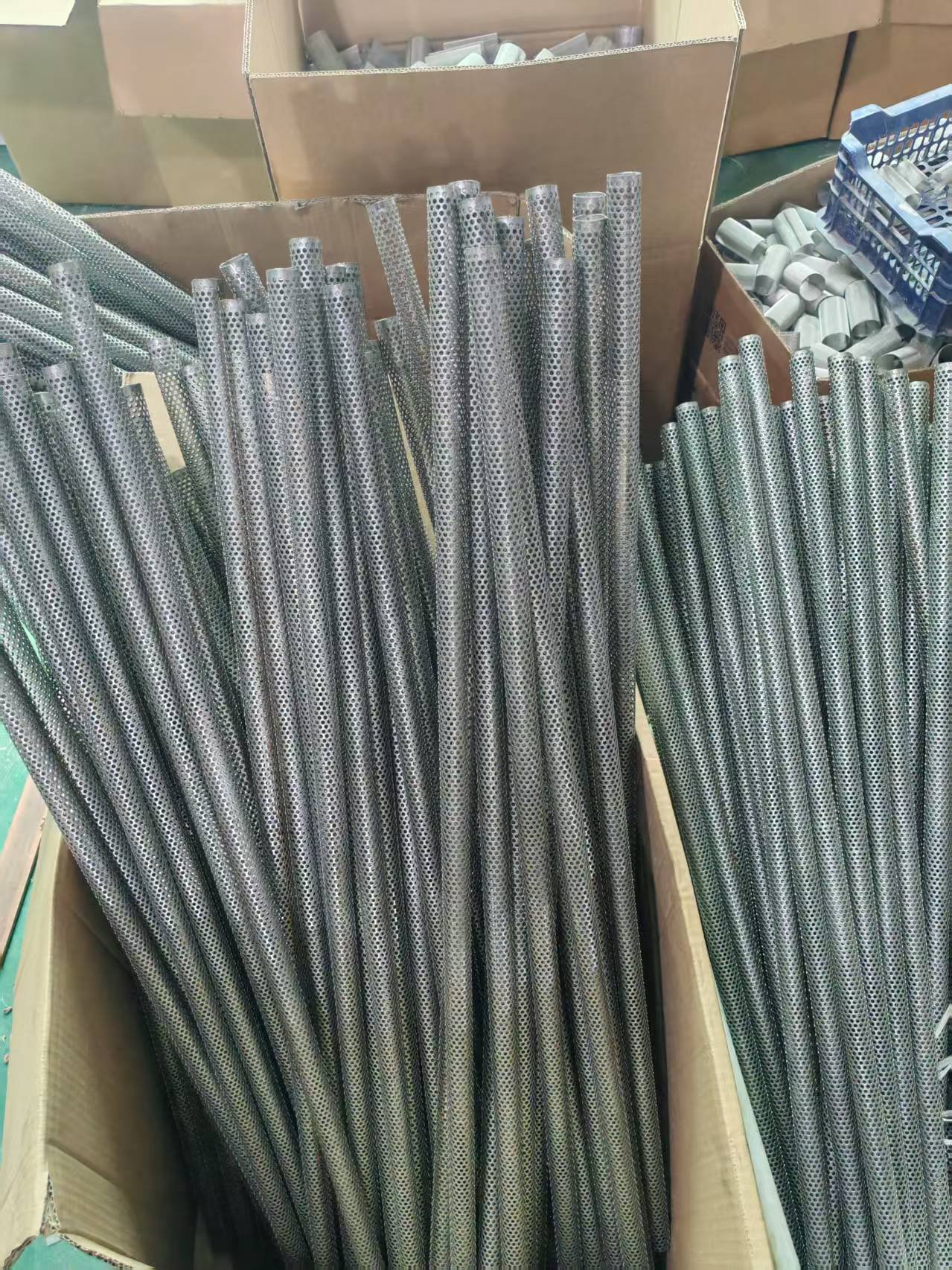
A perforated metal tube for industrial filters must be selected by its application, flow, differential pressure, temperature, filter media and assembly. Diameter, wall thickness, hole size, pitch, pattern, open area, material and welding must work together. Hole size alone is not a complete specification.
By Jack Sun. Our company is based in Anping, Hengshui, Hebei, China, a region known for wire mesh manufacturing. Jack Sun works in metal mesh weaving and industrial filter manufacture. This guide approaches tube selection from manufacturing and assembly.
Filter media need reliable support when exposed to differential pressure, vibration, pulsating flow and repeated cleaning. The question is which support tube fits the particular filter and operating conditions.
1. Select the Tube by Application
Liquid filtration
Consider flow, differential pressure, diameter, wall thickness, holes and media together. Fluid passing through an outer filtering layer also crosses the support structure. With comparable geometry and conditions, more available opening area can reduce local resistance, but actual pressure drop also depends on velocity through openings, edge shape, fluid properties and the complete element.
Oil and hydraulic filtration
Separate filtration rating from support design. The element can experience pressure changes and differential pressure across its media. Design the media and support separately, then validate the assembly.
Gas and dust filtration
A tube often provides an internal flow channel and supports woven wire mesh, sintered mesh or metal fiber felt. It usually does not form the final fine filtering layer.
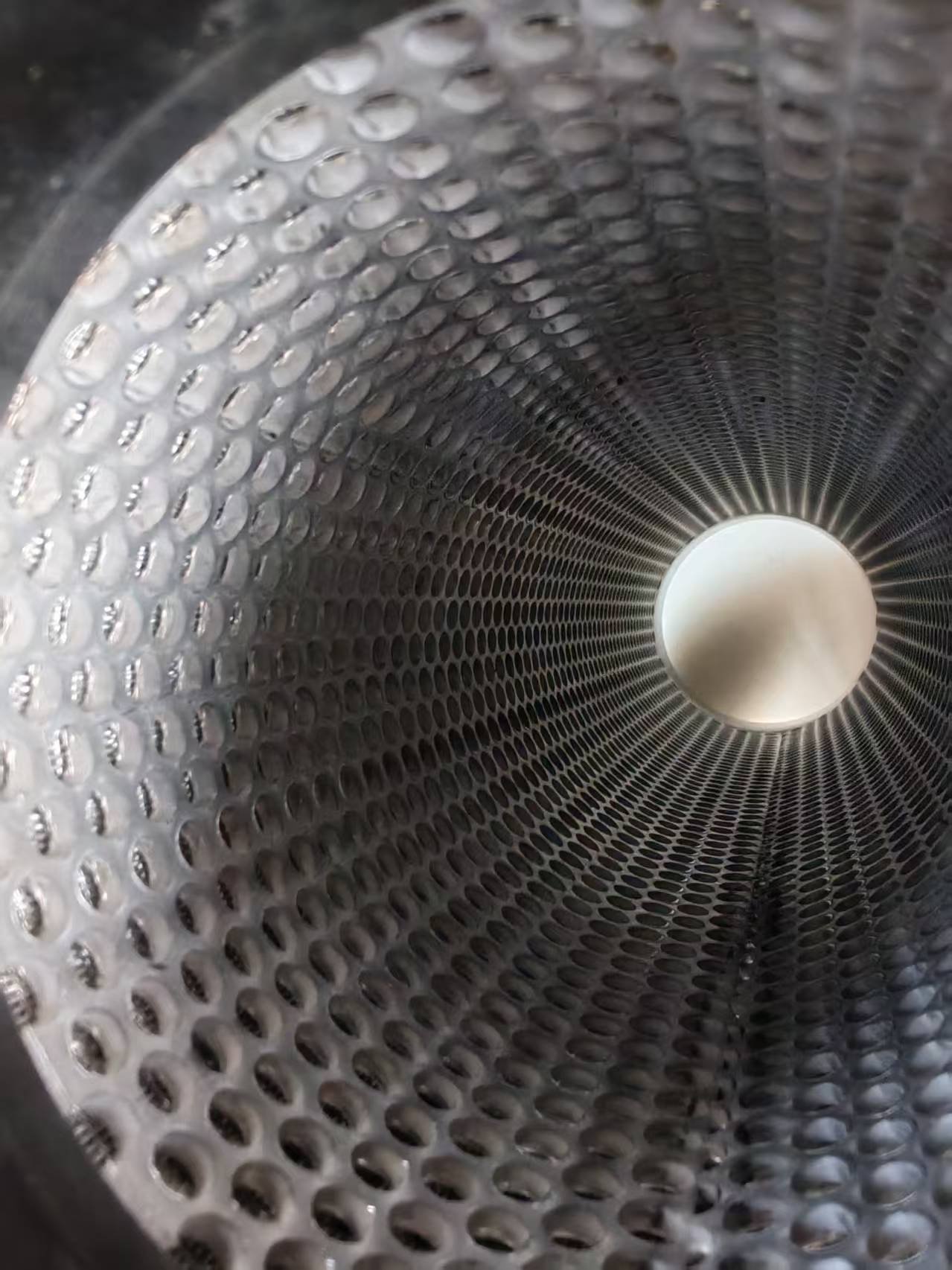
In a sintered metal fiber felt filter, the felt performs the main filtration duty. Support tube hole size does not equal the element filtration rating.
High temperature filtration
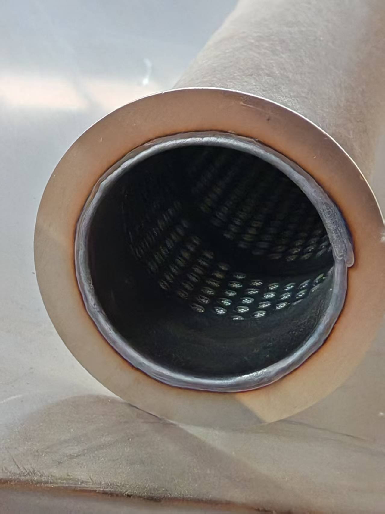
Assess normal and peak temperature, thermal cycles, oxidation, corrosion, expansion, cleaning loads, media and long term mechanical stability.
Coarse screening and prefiltration
Where the tube itself screens particles, opening size directly affects retention. With finer outer media, that media usually determines the final rating.
2. Establish Operating Conditions First
Flow
Define the required flow and fluid properties. Open area alone cannot establish the complete filter capacity.
Working pressure and differential pressure
System pressure and the pressure difference across the element are different quantities. The support must withstand its actual differential pressure and mechanical loads. A tube forming a pressure boundary requires engineering verification under applicable design codes and product standards.
Temperature and medium
Specify normal and maximum temperature, temperature cycling and thermal shock. Identify water, oil, hydraulic fluid, chemicals, air, flue gas, dust or another medium.
Particles, corrosion and cleaning
Provide particle size and shape for direct screening. For material selection, identify composition, concentration, pH, chlorides and exposure conditions. Specify gas backblowing, pulse cleaning, liquid backwashing, chemical or mechanical cleaning: these processes also load the support.
Media and installation
Identify woven mesh, sintered mesh, metal fiber felt, membrane or cloth, its thickness and rigidity, and whether it mounts inside or outside the tube.
3. Specify Key Dimensions
Diameter
Specify outside or inside diameter to suit the housing, media and mating components.
Wall thickness
Thickness affects stability, weight and forming. A thicker wall is not automatically better. Evaluate it with diameter, holes, material and loads.
Length
Match the element and equipment. Long tubes also require control of roundness, straightness, sizing, welds, transport and assembly.
Hole diameter
For support duty, holes serve open area and local support. For direct screening, they also participate in particle retention.
Pitch
Pitch P means center to center distance, not the gap between hole edges. For equal round holes of diameter D, the minimum planar ligament between adjacent holes is P − D. The same diameter at different pitches gives different open area and remaining metal.
Pattern
State hole shape, size, pitch and arrangement together on the drawing.
4. Compare Round, Square and Slotted Holes
Round holes are a common general option for filter supports. Square openings provide a different geometry, but do not inherently give higher flow. Slots require length, width, direction, pitch and ligament dimensions. Compare actual open area and remaining material, media contact, cleaning or vibration, installation and manufacturing stability.
5. Longitudinal and Spiral Welding
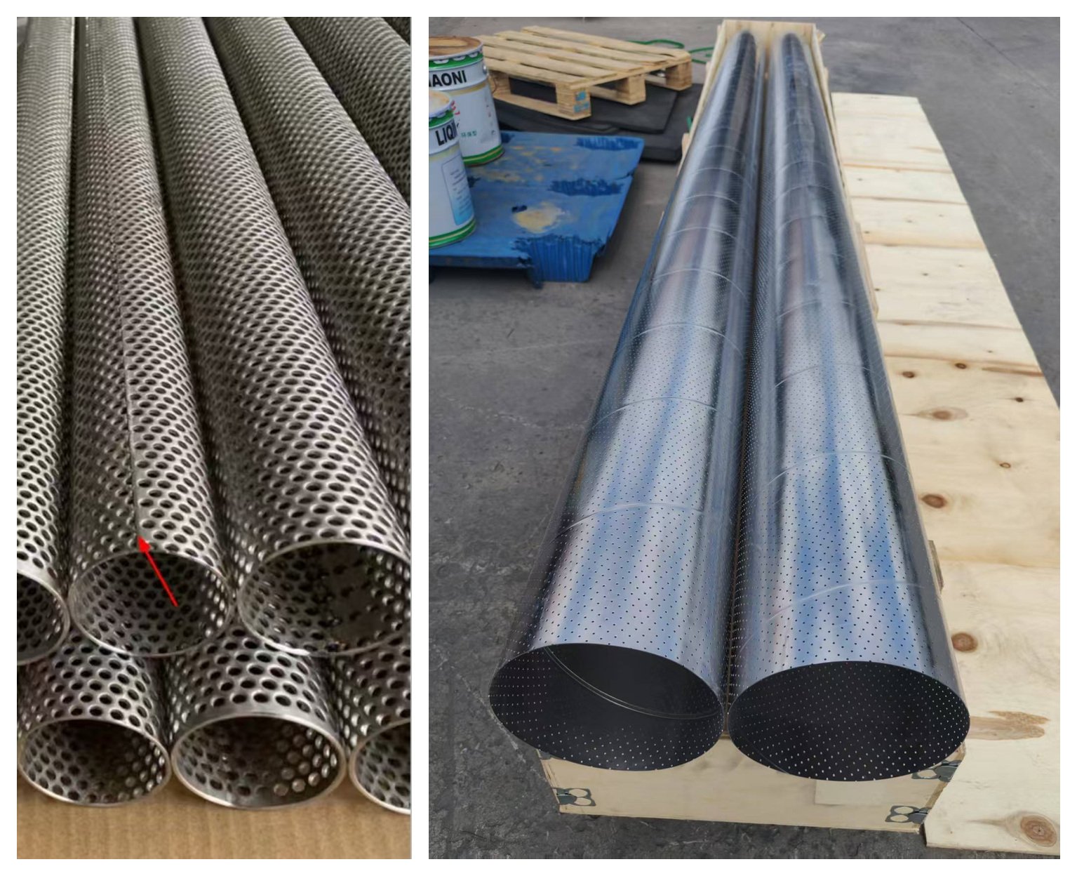
A longitudinal seam runs approximately along the tube axis; a spiral seam follows a helical path. Seam direction alone establishes neither strength nor pressure capability.
Longitudinal welded tubes
Evaluate this route where dimensional control, media fit and later processing are priorities. Accuracy also depends on stock, punching, forming, welding, sizing, straightening and inspection.
Spiral welded tubes
This route can suit particular diameters, lengths and stock widths. Check its effect on perforated regions, roundness, media mounting, supports, end machining, later welds and actual loads.
Choosing a route
Compare the specific product requirements and manufacturing capability rather than assigning a universal ranking to either seam.
6. Select Material for the Environment
304 stainless steel
A common material to evaluate for general industrial use, with useful formability and corrosion resistance. Suitability still depends on the medium and temperature.
316L stainless steel
Molybdenum generally improves pitting resistance in some chloride conditions compared with 304. It does not make 316L suitable for every chloride or corrosive environment. Assess composition, concentration, temperature, pH and exposure.
Carbon steel
An economical candidate for less corrosive conditions, subject to surface protection, temperature, service life and compatibility with other materials.
Special alloys and high temperature service
A grade designation alone is insufficient. Consider sustained and peak temperatures, cycling, oxidation, corrosion, cleaning and mechanical loads.
7. Calculate Perforated Tube Open Area
Open area is the geometric ratio of opening area to a stated reference area. It is not filtration efficiency, actual flow or final filter pressure drop.
Equal round holes in a 60° staggered pattern
For equal diameters and equal center spacing in the repeated planar pattern:
φ = 100 × (πD²/4) / (√3P²/2) ≈ 90.69 × (D/P)²
φ is a percentage. D and P use the same units and P must exceed D. The formula does not apply directly to straight rows, square holes, slots or other arrangements. It excludes unperforated ends, seam bands, spiral overlaps and obstructions in the finished tube.
Worked example
D = 3 mm and P = 5 mm give 32.65% theoretical open area and a 2 mm ligament. If that perforated region covers 90% of the reference surface without additional overlaps or blockage, overall open area is approximately 32.65% × 90% = 29.38%. Count boundary holes and partial openings from the actual drawing. The perforated tube effective open area calculator provides a geometry check; it does not validate strength or pressure drop.
Flow and finished geometry
Fluid properties, hole velocity, wall thickness, edge condition, media resistance, end connections and blocked regions affect flow. Always identify whether the quoted percentage describes the repeated pattern or the entire finished surface.
8. Balance Open Area, Thickness and Strength
Increasing open area reduces the remaining metal. A support exposed to high differential pressure, vibration or pulse cleaning needs adequate stability. Check diameter, thickness, ligaments, length, supports, welds, material and load direction together. Neither maximum open area nor maximum thickness is a universal target.
9. Manufacturing Changes the Result
A typical route is punching → rolling or spiral forming with welding → sizing and straightening, with finishing where required. Control burrs and sharp edges that may damage media, weld discontinuities, distortion, roundness, straightness and end dimensions. Inspect the finished component and assembly rather than relying only on incoming sheet specifications.
10. Common Selection Errors
- Choosing only by hole diameter and omitting pitch or pattern.
- Assuming greater open area is always better.
- Confusing support holes, mesh count and filtration rating.
- Ranking welds only by seam direction.
- Providing a material grade without operating conditions.
- Treating system pressure as the support tube differential pressure.
11. Information for Custom Perforated Tubes
- Inside or outside diameter, thickness, length, ends, roundness, straightness and tolerances.
- Hole shape, size, center pitch, pattern, perforated and unperforated regions, and reference open area.
- Material and surface requirements.
- Medium, temperature, pressure, differential pressure, flow, particles, cleaning and media installation.
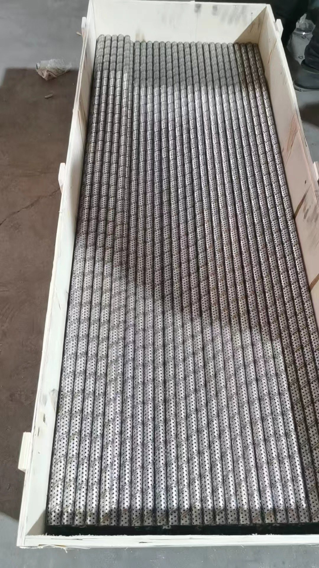
For replacements, supply drawings, an old sample, mating media and housing dimensions. If the old part deformed, clogged, damaged a weld or wore the media, assess the failure before copying it.
12. Frequently Asked Questions
Is the tube media or support?
It can be either. In many fine filters it is support; in coarse screens it also retains particles.
Should hole size equal filtration rating?
No. A support skeleton and its fine filtering layer have separate functions.
Do smaller holes always improve filtration?
Only direct screening makes hole size directly relevant to retention. Support holes alone do not define fine filtration.
What open area is appropriate?
There is no fixed percentage for all filters. Flow, media, dimensions, differential pressure and loads determine it.
Can it support high pressure filters?
Yes, subject to actual differential pressure and load verification. A pressure boundary requires applicable engineering calculations and validation.
How should 304 and 316L be compared?
Use the actual medium, corrosion conditions, temperature and cost. Neither grade covers every environment.
Which seam is better?
Compare dimensions, weld quality, tolerances, processing, fit and loads for the project.
Can tubes serve high temperature filters?
Assess suitable material, media, oxidation, thermal cycles, expansion, cleaning and long term stability.
Can an old tube be reproduced?
Yes. Measure more than diameter and length, and investigate any original failure.
What should a quotation include?
At minimum material, diameter, thickness, length and full hole pattern; add operating and assembly data for filtration duty.
13. A Practical Selection Sequence
Application → operating conditions → media → support duty → diameter and thickness → hole pattern → open area → structural stability → material and manufacturing. Parameters are interdependent. High pressure, high temperature, severe corrosion and pressure boundary applications need project specific engineering verification.
Discuss Your Filter Support
Provide your drawing, old sample or equipment data so we can evaluate dimensions, pattern, open area, material, welding and assembly together.
References
The open area expression is derived from round hole area and a triangular repeating cell. For corrosion boundaries, see Outokumpu: Corrosion resistance.