
By Jack Sun · October 13, 2026
Quick definition
Wire mesh defect inspection begins by recording visible conditions: broken or missing wires, changed interlacing, aperture variation, folds, edge issues and surface anomalies. Evaluate them against the confirmed specification, measurements and acceptance rules. A local photograph alone cannot establish batch acceptance, alloy identity or filtration performance.
One photograph shows diagonal openings; another shows projecting cut ends. Are both unacceptable? First establish structure, sample condition, edge requirement and intended location. Tension, viewing angle and normal processing can change appearance. A real break may also be hard to see under reflections or poor resolution.
This guide helps purchasing, manufacturing and inspection personnel record observations consistently. The illustrations are simplified square-opening projections, not microscopy, standard-body drawings or batch test results. Dutch weave, knitted, welded, coated and composite materials require checks suited to their own structures.
1. Identify structure and inspection object
Record product, material, weave, warp/weft specifications, dimensions and delivery condition. Ordinary square cloth, Dutch weave, pre-crimped mesh and knitted mesh have different normal appearances. Compare a doubled-wire or dense region with the agreed structure instead of evaluating every material against a plain-weave drawing.
Distinguish full rolls, cut pieces, cylinders, welded products and sintered media. They can have different edge and processing requirements. Mark cut ends, locating welds, bound edges and seams separately from critical filtering or visible service regions.
ISO 9044:2016 covers industrial square-opening woven cloth for screening within its scope. ASTM E2016-22 also identifies exclusions [1,2]. Neither is used here as a universal tolerance table for every metal mesh.
Specify whether observations are made relaxed, under a defined tension, laid flat or after forming. Flexible samples can show different opening shapes and dimensions under different restraint. Record sample condition with the measurements.
2. Identify common visible conditions
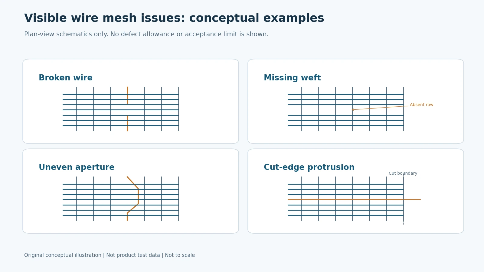
Original simplified projections of a broken wire, missing weft, uneven opening and projecting cut edge. These are concepts, not photographs or acceptance limits.
| Visible condition | What to observe first | What to confirm next |
|---|---|---|
| Broken wire | Interrupted wire path, local end or gap | Location, extent and relationship to processing |
| Missing wire/weft | A wire or segment absent from the agreed repeating sequence | Warp/weft direction, specification, missing length and number |
| Local duplicate or wrong interlacing | Pattern differs from the agreed weave | Intended design and any normal joining area |
| Loose wire | Different local path, raised wire or tension behavior | Observation condition, extent, direction and forming effects |
| Uneven aperture or spacing | Local net opening or arrangement differs from surrounding areas | Direction, method, measured dimensions and tolerances |
| Fold, crease or waviness | Visible fold line, raised area or uneven plane | Packaging, transport, forming and service location |
| Burr or projecting end | Metal projecting at a cut, edge or local area | Cutting process, edge requirement and subsequent assembly |
| Deposit or discoloration | Local coating, residue, stain or color change | Material, origin, cleaning condition and corrosion evidence |
These names describe observations, not automatic rejection. This guide does not invent an allowable number per square meter, a maximum gap or one appearance grade for all customers. Acceptance depends on product specification, function and agreed rules.
3. Broken wires, missing weft and weave pattern
Broken wire
Follow the wire path to verify a physical interruption. A dark spot or lost reflection alone is insufficient. View from another angle where useful, retaining front, back and magnified images. Locate the break within surrounding structure instead of keeping only an untraceable close-up.
Record whether the interruption is in the mesh field, edge, weld or formed region; whether one or several wires are affected; and whether there is a local tear. Manufacturing, cutting, transport, installation and service can produce similar appearances. A photograph does not establish one cause.
Missing wire or weft
Identify warp/weft direction and repeat sequence before recording a missing location. Missing weft may widen local spacing, but intentionally different warp and weft specifications need not appear square. Record missing length, surrounding mesh and sample location, using the approved drawing or a normal reference sample where available.
A larger local opening can affect function, but a photograph cannot quantify the entire element's penetration. Link structural observations in critical filtering regions to complete-element requirements.
Duplicate or incorrect interlacing
Plain, twill and Dutch weaves have different patterns. Compare local interlacing with the agreed weave. A pattern that is not one-over/one-under is not, by itself, evidence that twill or Dutch weave is defective.
Multiple-wire feed, different directional density and joining regions also need the product description. Record the visible repeat and the question needing confirmation instead of writing only “wrong process.”
4. Aperture variation, loose wires and folds
Distinguish net opening from center-to-center pitch. State direction and position. Perspective can make a square look trapezoidal or diamond-shaped, while shear, tension and forming can change the projection. Photographs locate observations; appropriate measurements establish dimensions.
Multiple positions help describe variation, and original readings should be retained. An average does not show local extremes or defect location and does not establish batch uniformity. Sampling coverage and quantity follow the inspection requirement rather than a universal scheme in this guide.
For loose wires, record mesh condition as well as raised paths, changed crossings or flatness. Photographs with different restraint cannot directly compare “tightness.” Cutting, forming and assembly may also change the state.
Keep folds, waviness and dimensional deviations separate. A crease does not prove every opening is outside tolerance. A flat surface does not prove every opening meets the specification. Record flatness, overall geometry, local openings and service regions separately.
5. Cut edges, burrs and surface condition
Cut mesh has wire ends; woven selvage and bound edges form differently. Confirm the agreed edge type before evaluating projecting ends, burrs or distortion. State whether the edge contacts a seal, filtering layer or assembly part.
Record cutting, welding, rolling and cleaning requirements separately, then compare the delivered state with the agreement. Neither “every sharp end is acceptable” nor “every cut edge must have no wire ends at all” is a universal rule.
Discoloration can relate to oxidation, contamination, deposits or treatment. Color observation does not confirm the cause. Record location and visible accumulation, while checking material identity and cleanliness requirements separately. The materials reference explains why magnetism and surface appearance cannot identify every grade.
For coated mesh, coating condition is a separate inspection from bare-mesh geometry. Adhesion, bending and fluid exposure require their agreed methods and actual specimens. A bare-mesh visual guide is not a coating performance report.
6. Photograph and measure traceable evidence
Use the guide to how to measure mesh count, single-wire diameter and clear aperture when collecting dimensional evidence. Record direction, sample condition and local deformation; a calculated average is not a substitute for documenting an abnormal opening.
Start with an overall view, then both faces, edges and local observations. Include a reliable scale, reduce reflections and describe tension during photography. Add side views or different light angles for ambiguous features instead of enlarging one blurred image.
Link each image to sample ID, location, direction and observation number. Gauge photographs should show measurement position and reading with units. Keep the scale near the target plane. Pixel lengths in oblique photographs are not precise dimensions.
Record cleaning, flattening, trimming or forming before and after observation. Initial inspection need not cut open an intact sample. Preserve the original condition before agreeing on sectioning or other destructive examination.
Measurements also require instrument, calibration, resolution, contact method and relevant environment. Displayed decimal places do not establish actual accuracy. Fine mesh, flexible structures and close tolerances require suitable methods and fixtures.
7. Turn observations into an inspection record
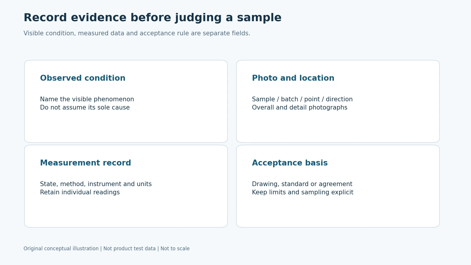
Original conceptual diagram: visible condition, measured data and the acceptance rule are separate fields.
Separate “what was seen,” “what was measured” and “the basis of the decision.” An observation might be “successive weft spacing increases in region B.” The measurement field holds readings and method; the decision field identifies the drawing, clause or agreed rule and preserves unresolved items.
Include sample/batch, grade and certificates, weave, warp/weft specification, delivery condition, location map, photo references, extent, measurement method/readings, acceptance basis, proposed action and review result.
A single local feature and a batch conclusion require different evidence. A sampling conclusion needs its coverage. Repaired or selected material needs its new condition recorded. Raw-material certificates, mesh dimensions and complete-filter performance have different roles; one acceptable result does not prove all others.
For drawing-based work, use confirmed tolerances and critical regions. For a new project, define function first. Sample-based work reconstructs measurable structure and separately establishes material and performance that appearance cannot reveal. Use the wire mesh specification guide and standards index to organize requirements.
8. Frequently asked questions
Can one photograph establish that a roll is acceptable?
No. Confirm specification, coverage, measurements and acceptance basis.
Is a diamond-shaped opening always defective?
Viewing angle, restraint, structure and forming can change its appearance.
Is every cut edge with wire ends unacceptable?
Evaluate the agreed edge form and service location rather than one universal appearance rule.
Can a plain-weave illustration be used to inspect Dutch weave?
The structures differ. Use a matching specification and method.
Can an acceptable average aperture override a local anomaly?
Apply the relevant local requirements, measurements and sampling rules.
Does discoloration prove the wrong material grade?
No. Verify material and visible surface condition separately.
Why use conceptual drawings instead of defect photographs?
This edition uses clearly identified concepts to explain observation terms. They are not actual defects or batch evidence.
Is there one allowable defect count for all mesh?
No universal count is specified here. Product, region and acceptance requirements differ.
Summary
Establish structure and condition, then record observations, measurements and decision criteria. Concepts explain what to look for, and photographs document an actual sample; neither replaces specifications and complete inspection. Keep local observations separate from batch conclusions.
References and illustration basis
- ISO 9044:2016 official catalog, square-opening screening cloth scope.
- ASTM E2016-22 official catalog, industrial woven cloth scope and exclusions.
Descriptions, photographing steps and record organization are editorial guidance, not a universal inspection procedure prescribed by either standard. The two original drawings contain no tolerances or pass/fail decisions.
Author background: Jack Sun has long worked in metal wire mesh weaving and industrial filter element manufacturing. Our company is based in Anping, Hengshui, Hebei, China.
For manufacturing-stage investigation and prevention, read woven wire mesh defects: causes and prevention.
For order review, traceability, production checks and delivery records, read woven wire mesh quality control.