By Jack Sun | Updated October 17, 2026
The main difference is the structure: sintered wire mesh is built from woven metal mesh layers, while sintered metal fiber felt is built from a network of metal fibers. This article compares multilayer mesh and fiber felt used in filter elements, from their structure to the conditions needed for a useful performance comparison.
Start with the structure your application needs, then compare retention, flow resistance and cleaning performance on the same basis. If your drawing specifies woven filtration and support layers, evaluate a matching sintered mesh construction. If you are evaluating filtration within a fiber network, include a suitable fiber felt construction. Neither name alone identifies the better filter.
1. What Is the Difference Between Sintered Wire Mesh and Metal Fiber Felt?
In multilayer sintered wire mesh, woven layers provide the filtration structure and the required protective or support functions. In sintered metal fiber felt, metal fibers form an interconnected porous network, with contact points bonded by sintering. Mesh count and weave describe the first structure; fiber size and the way the network is laid describe the second.
| Feature | Sintered wire mesh | Sintered metal fiber felt |
|---|---|---|
| Building blocks | Woven metal wires | Metal fibers laid into a porous network |
| Structure to specify | Mesh count, wire diameter, weave and layer sequence | Fiber size, network or layer arrangement, thickness and pore structure |
| Support arrangement | Filtration and support mesh layers combined to the design | Fiber medium with any specified mesh backing or element support |
| First drawing check | Which layer filters, which layers support, and the intended flow direction | Fiber-medium construction, any backing, and the intended flow direction |
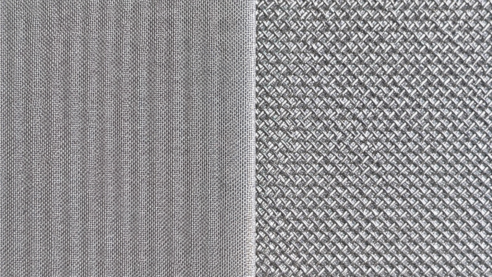
Five layers are a common mesh configuration, but layer count follows the design. Fiber felt can also use different layers or mesh support. Specify the actual construction rather than assuming every mesh has five layers or every felt has a graded pore structure.
Both descriptions concern structure, not alloy grade. Compare the specified metal grade with the fluid composition and temperature conditions when assessing material compatibility.
2. When Should You Consider Each Medium, and What Are Its Limits?
Start with how particles need to be captured, how deposits will be removed, and how the finished element will carry its loads. The following conditions help narrow the choice; they are not universal performance rankings.
When to consider sintered wire mesh
Consider a suitable mesh laminate for reusable filtration where a defined woven filtration layer, supporting layers and stable element geometry are priorities. For a surface-filtration design, it is a useful candidate when deposits can be released from the upstream face during the planned cleaning cycle. Verify this with the actual contaminant and the proposed layer sequence.
Limits and next check: Additional support layers can contribute flow resistance. Fine particles, sticky deposits or gels may still lodge in the structure, so a woven construction does not guarantee easy backwashing. Compare clean-state resistance, loading and recovery. Layer count or sheet thickness alone does not establish retention or finished-element pressure capacity.
When to consider sintered metal fiber felt
Consider fiber felt when you want to evaluate particle capture within a porous fiber network, or a pleated design that adds filtration area within a limited installation space. Fiber size and layup can be selected for the required filtration task. Felt can be designed for surface or depth filtration; the operating mode depends on the construction and contaminant.
Limits and next check: Contaminants trapped within the network can be harder to remove than a releasable surface deposit. Confirm whether offline cleaning is needed and measure recovery before reuse. High porosity does not by itself prove lower pressure drop or greater dirt-holding capacity. Check backing, pleat spacing and the finished support arrangement against forward and reverse loads.
Turn the conditions into a selection check
Use the table below to connect your starting requirement with the information needed next.
| Your requirement or question | Starting point | What to verify next |
|---|---|---|
| The drawing specifies woven filtration and support layers | Evaluate the matching sintered mesh layer construction | Weave, layer order, retention target and finished support arrangement |
| You want to evaluate capture within a fiber network | Include an appropriate fiber felt construction in the comparison | Retention, loading behavior and cleaning recovery for the actual contaminant |
| You need lower pressure drop or a longer loading cycle | Compare suitable designs from both groups | Pressure-drop and loading data at a common filtration target and flow basis |
| The element will be backwashed or exposed to reverse pressure | Review the complete element drawing before choosing the medium | Load direction, support, connections, seals and cleaning recovery |
| You are replacing an existing element with the same micron label | Confirm the rating definition and installation details first | Retention test, dimensions, interfaces, service conditions and failure history |
When is a change of medium worth investigating?
If pressure drop rises too quickly, cleaning recovery declines, or an element deforms or leaks, first identify the cause. Review flow, temperature or viscosity changes, contaminant loading, cleaning records, seals and supports. A different medium is worth trialing when its proposed construction addresses the identified problem; changing the material name alone does not resolve a flow, installation or support problem.
Do not substitute by micron label alone. Match retention criteria, dimensions, interfaces, allowable differential pressure and cleaning conditions. Validate the replacement against those requirements before routine use.
Check the limits shared by both. Gas or liquid service alone does not decide the choice. Temperature and corrosion suitability depend on the specified alloy, process chemistry, welds and seals; load capacity depends on the complete element. For sticky or difficult-to-remove contamination, test cleaning recovery or plan a replacement interval before selecting either medium for reuse.
3. Do the Micron Ratings Mean the Same Thing?
Two elements labeled “10 microns” are not automatically interchangeable. Establish whether the number is a nominal rating, a particle size at a stated retention efficiency, or a pore-test result. Then compare the test particles, fluid, flow, sampling method and efficiency criterion.
Porosity describes void space; it does not by itself establish particle retention. A bubble-point result is also different from a particle-retention result. ISO 4003 describes bubble testing as a quality-control method, with limitations on using it to define filter grades or exact pore-size distributions. [1]
Record whether each result refers to a media sample or a complete cartridge. A finished element also includes seams, ends and sealing paths. Where methods differ, identify the gap before treating the values as equivalent.
4. How Should You Compare Pressure Drop and Dirt-Holding Capacity?
Compare clean-state flow resistance first
Pressure drop is the pressure difference across the specified medium or element during flow. For a useful comparison, state the fluid, temperature, flow rate, effective filtration area, thickness, support arrangement and flow direction. Compare designs intended to meet the same retention target, and document the structural differences.
Superficial velocity: v = Q / A
Q is volumetric flow rate and A is the stated reference filtration area. For example, m³/s divided by m² gives m/s. This is an area-based average, not the local velocity inside a pore.
For pleated elements, define effective area and consider flow distribution. Equal outside dimensions do not establish equal filtration areas. ISO 4022 describes permeability testing for interconnected porous sintered metal materials; confirm the method’s scope for the sample geometry. [2]
Then compare loading and recovery
Dirt-holding capacity is meaningful only with the contaminant, particle-size distribution, concentration, feeding method and endpoint stated. Identify whether the result is per unit area or per complete element. Compare the pressure-drop rise during loading as well as retention at the endpoint.
Particles can deposit on or within a medium according to its structure and the contaminant. To decide whether a candidate improves the loading cycle, compare loading data under relevant conditions, followed by cleaning and recovery checks. Porosity or a generic claim of “high capacity” is not a substitute for that comparison.
5. How Do Element Construction and Cleaning Affect the Choice?
The medium becomes part of a plate, disc, cylinder or pleated cartridge. Confirm the support spacing, welds, end caps, connections and seals against the drawing, including forward and reverse differential pressure. These details determine how the finished element carries the specified loads.
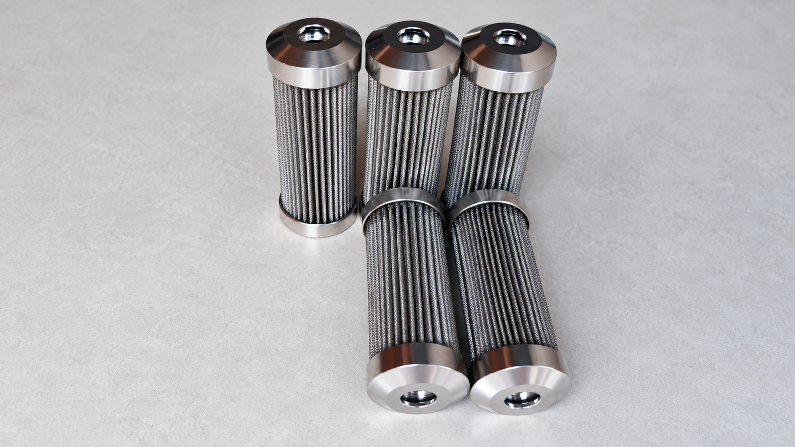
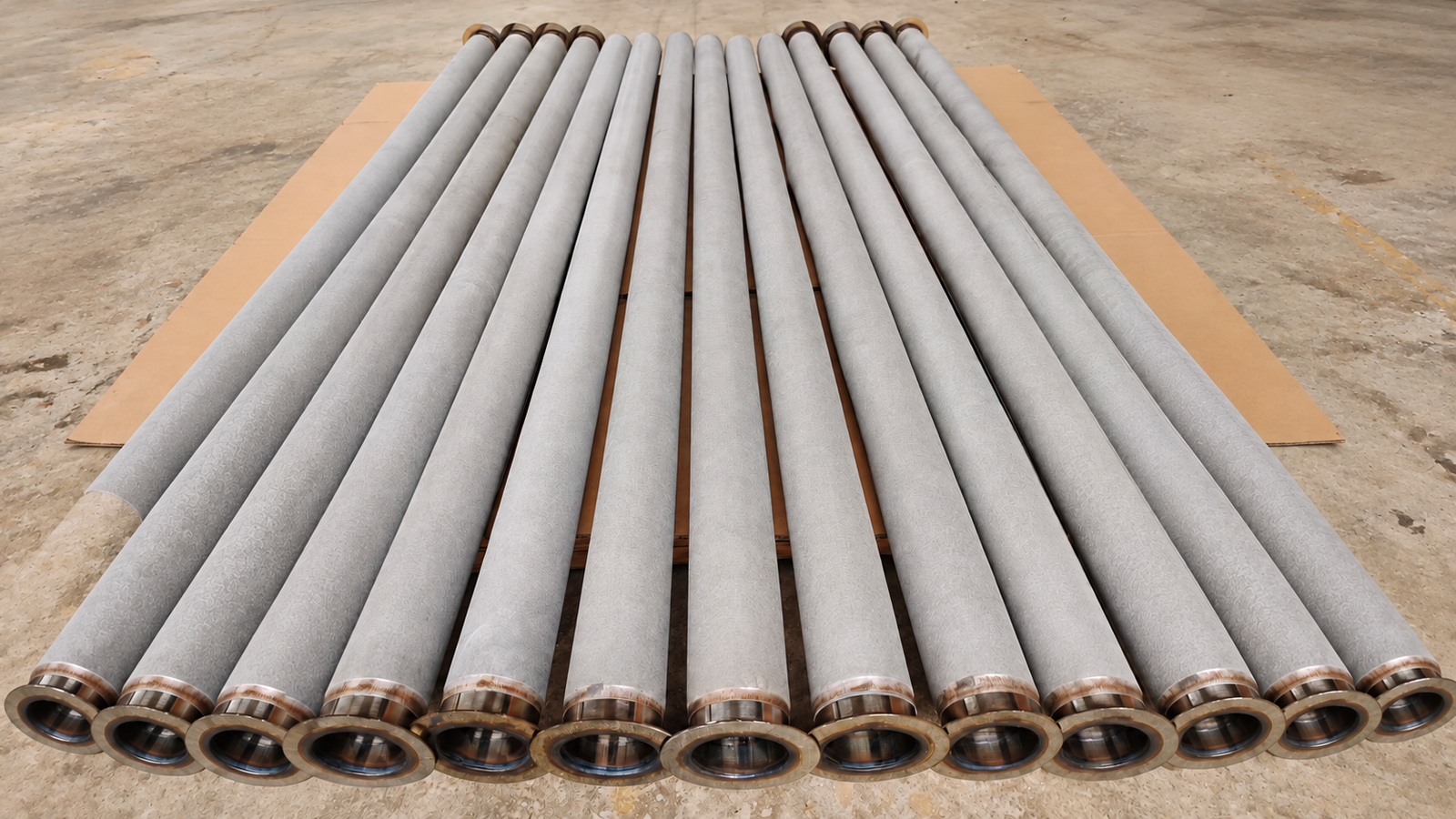
Cleaning suitability has two parts: the construction must tolerate the method, and the method must remove the actual contaminant. Check compatibility of the cleaning fluid with the medium, welds and seals. Review the applicable conditions for backwashing, chemical cleaning, ultrasonic cleaning or gas-system pulse cleaning rather than transferring one process directly to another service.
Agree on recovery checks before reuse: integrity, flow and pressure drop under repeatable conditions, and the required retention performance. A clean-looking surface alone does not establish recovery. If an element leaks or deforms, examine the failure and its load path before switching between mesh and felt.
6. What Information Makes the Comparison Useful?
Bring the requirements into one specification so that the proposed media and complete elements can be compared against the same task.
| Information | Details to record |
|---|---|
| Process fluid and contaminant | Composition, relevant viscosity, temperature range and contaminant characteristics |
| Retention target | Particle-size range, required efficiency and test method |
| Flow and loads | Normal and peak flow, allowable pressure drop, flow direction and reverse conditions |
| Drawing and installation | Dimensions, supports, connections, sealing surfaces and removal space |
| Material and cleaning | Metal grade, cleaning fluid, method and recovery requirements |
| Acceptance | Inspection object, methods, criteria and required records |
For a new design, use these inputs to screen the medium and element construction. For replacement, add the existing drawing or sample and operating or failure records. For purchasing, check that competing proposals state the same rating basis and acceptance requirements. A sample is useful for geometry and visible features; service and test records provide the performance context.
For available supply forms and fabrication options, see our sintered mesh filter elements and sintered metal fiber felt product pages.
7. Short Answers to Common Comparison Questions
Is sintered metal fiber felt always better for gas filtration and mesh for liquids?
The names do not define an exclusive gas or liquid application. Evaluate the fluid, contaminant, alloy, complete element and cleaning arrangement for the specific service.
Does a higher porosity mean better filtration?
Porosity and particle retention answer different questions. Check the specified retention target and the measured flow or loading behavior instead of ranking filters by porosity alone.
Can I choose by the sheet thickness alone?
Use thickness together with the specified mesh or fiber construction and its support. Thickness alone does not define pore structure, retention or the load capacity of a finished cartridge.
Choosing Between the Two
Use sintered mesh as a candidate when the design calls for a woven-layer construction; include fiber felt when the design calls for a fiber-network medium. When the goal is lower resistance, greater loading capacity or better cleaning recovery, compare suitable candidates on the same retention and operating basis. Finish the decision at the element level by checking supports, connections, seals and the agreed verification results.
About the author: Jack Sun works in metal wire mesh weaving and industrial filter element manufacturing in Anping, Hengshui, Hebei, China.
Technical References
- ISO 4003:1977 — Permeable sintered metal materials — Determination of bubble test pore size. Public abstract: bubble-test purpose and limitations.
- ISO 4022:2018 — Permeable sintered metal materials — Determination of fluid permeability. Public abstract: permeability method and sample-scope limitations.
These references use the public abstracts, not the full paid standards. They describe test methods, not a claim that a particular supplied model has been tested or certified to them.