
By Jack Sun · Filtalloy · October 19, 2026
A roll of metal wire mesh can become a narrow strip, a rectangular sheet, a disc or a shaped component. The outline may look simple, yet several changes occur near the cut: wires are severed, local interlacing restraint changes, openings may be pulled out of shape and the edge may lift.
Understanding how to cut wire mesh therefore involves both producing the required outline and preserving the structure around it. Shearing, slitting, punching and laser cutting separate material in different ways, with different edge conditions to consider. [1][2][3]
This guide mainly concerns woven metal wire mesh. It follows the material from method selection and support through cutting, edge treatment and inspection. Sintered, welded or coated materials need additional consideration of their bonding and surface condition.
Why cutting changes the mesh edge
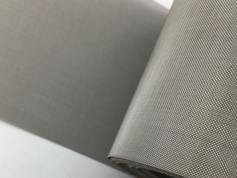
Warp and weft wires interlace to form woven mesh. In ordinary as-woven cloth, the crossings are not all welded or sintered together. Their restraint comes from the weave geometry and contact between wires. [4]
A cut severs some wires beyond their last remaining crossing. Material that previously continued into a larger woven structure is removed, changing the restraint near the boundary.
Consider a weft wire at an edge. Before cutting, it interlaces within continuous mesh. Afterwards, its end lies closer to a free boundary. Its response to pulling or rubbing depends on the remaining interlacing, wire condition and any subsequent restraint.
Severing the wires does not automatically stabilise the new edge. Some cut pieces can be used as they are; others need binding, a frame or a suitable joining process.
Projecting ends, burrs and fraying are different observations
| Observation | What is present? | Useful distinction |
|---|---|---|
| Projecting wire ends | Severed wire ends extend near or beyond the outline | An otherwise clean wire end can still project |
| Burrs | Small raised or sharp metal features at the cut | A whole projecting wire is not necessarily a burr |
| Loose wires or fraying | Edge wires move, slip or leave the weave | The issue mainly concerns restraint and structural stability |
| Curl or edge lift | The edge departs from the original plane | Loading, existing curvature and thermal effects need consideration |
These can occur together. Deburring an edge does not necessarily secure a loose wire. Holding an edge flat does not establish that the cut face has improved.
Mesh characteristics that affect cutting
Mesh count is only a starting point. Wire diameter, weave, overall thickness, material condition and additional bonding also affect processing.
The cutting path crosses wires, openings and intersections
A tool moving through mesh encounters a discontinuous structure. Its path may cross individual wires, open spaces and intersections. That differs from progressing through continuous solid sheet.
Wire diameter affects the conditions needed to sever each wire. Opening size and arrangement affect how the structure is distributed along the path. Equal-count square meshes can use different diameters, so count alone cannot establish whether a hand tool is suitable or whether another mesh's settings will work.
Weave and bonding affect edge movement
Square, Dutch and other weaves differ in crossing pattern and wire arrangement. A dense appearance does not automatically establish resistance to fraying. The relevant question is what interlacing and restraint remain near the cut.
Mesh with sintered, welded or other bonded crossings can behave differently from ordinary as-woven cloth. Its cut-edge performance should not be generalised to every woven structure.
Cutting direction affects the resulting boundary
Cuts along the warp, along the weft and at an angle intersect different wire segments and crossings. Angled or curved paths may leave short ends of varying lengths.
Two pieces with the same outline can therefore have different edge appearances if the mesh orientation differs. Direction also deserves attention when a piece will be bent, folded or placed in a frame.
Hardness, ductility and existing roll curvature need to be considered with the structure. A material name such as stainless steel or copper is not a complete description of its cutting behaviour.
How the main wire mesh cutting methods work
Hand shearing
Hand shears separate wires through the relative movement of cutting edges. Suitable tools can handle some small pieces, simple outlines or local trimming, provided their rated capacity matches the material, diameter and structure.
A common difficulty is controlling the mesh through successive cuts, pauses and turns. If the tool pushes or drags the fabric before severing the wire, the surrounding area can bend or skew.
Being able to cut a short section does not demonstrate control of a long straight edge, a fine curve or repeated parts. The outline, surrounding mesh and consistency all deserve observation.
Mechanical shearing
Mechanical shears can be used for straight cuts and sheet preparation. Blade interaction severs the metal; support and positioning near the blades influence whether unwanted movement accompanies the cut. [1][5]
Burrs or edge deformation call for consideration of blade condition, clearance, material and support. General metal-cutting principles apply, but the openings and interlacing mean that a clearance rule for one solid sheet should not be treated as a universal mesh setting. [5]
A sharper blade may leave a poor-clamping problem unresolved. Increasing clamping pressure without assessing its effect can likewise mark fine mesh or alter local openings.
Slitting
Slitting converts a wide mesh roll into narrower continuous strips and is a common further-processing route. [2]
Alongside cut position, the feed, guidance, cutting station and take-up have to work together. One correct width measurement does not establish a uniform strip along its entire length.
From a loading perspective, unstable guidance, sideways movement or uneven take-up can disturb the outline and relaxed condition. A wavy strip warrants examination of the continuous handling process as well as the blade.
Punching and blanking
Punching or blanking can produce discs and repeated profiles. The term depends on the operation and whether the retained part or removed material is being described. Tool geometry, die interaction, support, hold-down and stripping all contribute to the result. [1]
A complete circular outline is only one observation. Cut faces, loose wires and mesh condition also matter. Fine fabric can distort if it is dragged during the operation. With layers, their relative positions need separate attention.
An irregular result should not automatically be attributed to blunt tooling. Clearance, wear, support and stripping can all contribute, depending on the material and equipment. [5]
Laser cutting
Laser cutting concentrates energy locally to melt or vaporise material and form a kerf along a programmed path. It does not use a blade pressed into the mesh and can produce curves and complex outlines in suitable materials. [3][6]
Contact-free cutting still requires suitable workpiece support, and it is not a promise of zero thermal effect. Holding conditions, focus, energy delivery, travel speed and associated process conditions affect the result.
Relevant observations include resolidified material, local discolouration and distortion. Equipment manufacturers describe cutting quality as dependent on several parameters; material and operating conditions also affect dross and thermal distortion. [5][6]
Some materials and process combinations may produce a useful stabilising effect at the edge. The word laser alone does not establish that every end is secured or that all nearby crossings have equivalent bonds.
Comparing methods by task and result
| Method | Typical task direction | What to observe |
|---|---|---|
| Hand shearing | Small pieces, simple outlines, local trimming | Tool capacity, changes at each cut and movement of the mesh |
| Mechanical shearing | Straight cuts and sheet preparation | Blades, clearance, local support, burrs and edge deformation |
| Slitting | Continuous strips | Width along the length, guidance, edges and take-up condition |
| Punching or blanking | Discs and repeated profiles | Tool interaction, hold-down, stripping and layer positions |
| Laser cutting | Curved or shaped outlines in suitable materials | Support, kerf, resolidified deposits and local thermal effects |
This comparison explains different mechanisms. Suitability still depends on the mesh and an assessment of the actual cutting result.
Unrolling, support and positioning
The material's condition before it reaches the cutting point influences the finished piece.
Natural flattening and stretching are different states
A mesh roll can retain curvature when opened. If it is pulled into another shape for marking or positioning, the outline is established in that loaded state. Once released, its shape and openings may change again.
It is useful to distinguish ordinary unrolling, appropriate positioning and stretching. Holding down an existing sharp crease does not demonstrate that the material there has the same condition as the surrounding mesh.
Restraint needs to suit the cutting area
Without suitable local support, cutting forces may bend, displace or pull the fabric before separation. A mesh can be fixed securely at a distant point while remaining easy to move near the cut.
Support and holding positions therefore need to be considered in relation to the cutting area. Greater clamping force does not automatically prevent local distortion. Poorly positioned restraint may concentrate movement into a smaller region.
Position the outline relative to the weave
For a rectangular piece, the relationship between its sides and the warp and weft can affect appearance and subsequent handling. With discs and shaped components, the contour also passes through different wire segments and crossings.
If a particular edge condition matters, establish what boundary is being considered: the intended outline, the furthest projecting wire end or the position of an intact wire. Switching between them during measurement can produce inconsistent conclusions.
Common cutting problems and possible mechanisms
Burrs or sharp projections
Mechanical separation produces a local cut face whose form depends in part on blades, clearance and material condition. After thermal cutting, wire ends also need to be distinguished from attached resolidified material. [5]
First identify the feature: an entire wire end, a small raised cut edge or an attached particle. They are different targets for finishing. Magnified observation is more useful than running a bare finger along a sharp cut edge.
Loose wires and fraying
Here the main issue is restraint. Relevant factors include remaining interlacing, pulling during cutting, subsequent handling and any treatment that fixes the crossings.
An intact outline immediately after cutting does not establish stability through handling, forming and assembly. Where edge stability matters, the later process belongs in the assessment.
Removing one loose wire does not demonstrate that adjacent wires are secure. The need for additional restraint depends on the structure and how the part is used.
Edge lift, curl or local bending
Possible contributors include existing roll curvature, local shearing loads, clamping, movement during the cut and thermal effects. When the change appears is useful information: before cutting, during separation or only after removal from the work surface.
If the whole piece was pulled during cutting, its relaxed shape also needs to be distinguished from deformation caused by separation. Repeatedly pressing an edge down may leave the original cause unresolved and introduce further local damage.
Skewed openings or inconsistent outline measurements
Movement or local stretching can affect both the openings and the contour. Adjusting the cutting path alone may not correct the relaxed shape of the piece.
A mesh boundary is also discontinuous. One measurement position may meet a wire end and another an opening. A defined observation boundary is needed instead of changing the reference point from place to place.
Discolouration or deposits after laser cutting
Local heating, removal of molten material from the kerf and associated processing conditions can contribute to these effects. [5][6]
Colour, dross and bonding are separate observations. A pale-looking edge does not establish suitability for a particular function. Local fusion does not demonstrate that every neighbouring wire has been stabilised.
Assessment should relate to the intended use: are effective openings, subsequent forming, joining, surface treatment or contact with another component affected? Colour alone is not a universal accept-or-reject criterion.
What different edge treatments achieve
Finishing should address an identified need. Removing projections, restraining wires and supporting a component have different purposes.
Trimming and cleaning
Trimming can address unwanted wire ends, local burrs or other projections. Cleaning addresses loose fragments and deposits introduced or retained during processing.
Fine mesh needs protection during both. Excessive grinding, pulling or aggressive cleaning can extend an edge problem into the neighbouring fabric. Afterwards, inspect the edge and adjacent openings rather than only confirming that a visible projection has disappeared.
Binding and frames
Binding can cover and restrain a cut edge. A frame may also locate and support the mesh and provide an installation interface. The design depends on the component's function.
Covering the boundary does not by itself establish that the mesh is secure inside it. The holding method still has to suit the fabric. Edge treatment also occupies space and can change the final outline, thickness or usable area.
Welding and other bonds
Suitable welding or bonding can add restraint at selected positions. Its effect depends on material, wire size, contact and processing conditions. Fine mesh also requires attention to local burn-through, distortion and possible effects on passages.
Securing an edge does not alone establish the pressure capacity, filtration performance or sealing of a complete component. Those are separate functional questions.
Published mesh-belt examples illustrate how edge treatments can restrain wires in particular applications. Specially bonded mesh can also be prepared before cutting to improve edge stability. These are defined processing routes, rather than inherent properties of all woven mesh. [7][8]
Inspecting the cut piece
The result can be considered through four views: outline, cut boundary, neighbouring fabric and subsequent fit.
| Observation area | Questions to answer |
|---|---|
| Outline | Are dimensions, shape and weave orientation assessed against a consistent reference? |
| Cut boundary | Are there projecting ends, burrs, loose wires or attached deposits? |
| Neighbouring fabric | Have openings skewed, or have drag marks, creases, flattening or signs of local heating appeared? |
| Subsequent fit | Does the edge enter its frame, binding or assembly position as intended, and does ordinary handling change it noticeably? |
A correct outside diameter or width does not establish edge stability. A tidy edge does not replace observation of the nearby openings.
For flexible pieces, specify the state in which measurements are taken: naturally relaxed, appropriately supported or held in a defined fixture. Mixing loaded and relaxed measurements creates ambiguity.
Dimensional, edge and cleanliness requirements depend on the mesh and use. A single allowable value does not cover every woven structure. The wire mesh specification guide explains the starting material; the woven mesh defects guide helps distinguish weaving irregularities from changes introduced during cutting. For the earlier stages, see the woven wire mesh manufacturing process.
Frequently asked questions
Can ordinary scissors cut wire mesh?
Some fine, readily cut materials can be handled by suitable hand shears, but thin appearance is not a tool-capacity rating. Check the tool's specified materials and capacity and observe whether it cuts cleanly rather than dragging or folding the fabric. Household scissors should not be assumed suitable for metal mesh generally.
Why does a cut edge fray while the middle remains intact?
Cutting creates wire ends and removes part of the surrounding interlacing. The interior retains continuous woven restraint. Fraying also depends on the weave, wire condition, cutting method and later handling; one factor alone is not a complete explanation.
Does laser cutting eliminate burrs and heat effects?
No universal guarantee follows from the method. Laser cutting can produce high-quality edges, but the actual result depends on the mesh, equipment and processing conditions. Projections, resolidified deposits and thermal effects need separate attention.
Does every cut edge need welding or binding?
No. Treatment depends on structure, handling, assembly and whether loose wires or projections would affect function. Each additional operation should have a defined purpose.
Can several mesh layers be cut together?
That depends on the equipment, support, restraint between layers and their materials and structures. Stacking does not ensure that layers remain aligned. Inspect the individual layers for displacement, loose wires and contour changes; a successful single-layer cut does not validate a multilayer process.
Can pulling the mesh flat restore distorted openings?
The mechanism needs to be understood first. Roll curvature, weave movement, sharp creases and permanently deformed wires are different conditions. Pulling can change appearance temporarily or further alter openings, so it is not a universal repair method.
Cutting converts continuous mesh into a useful outline while creating a new structural boundary. Understanding how the chosen method separates the material, then examining wire ends, cut faces, restraint and nearby openings, makes edge problems easier to distinguish and address for the intended use.
Technical references
1. BOPP — Cutting and Punching: mechanical processing and fine-mesh edge quality.
2. BOPP — Cutting and Slitting: continuous strip processing.
3. BOPP — Laser Cutting: laser profile cutting of mesh; published machine dimensions and tolerances are not adopted here.
4. Cleveland Wire Cloth — Wire Cloth Glossary: interlacing, crimp, wire directions and selvage terminology.
5. AMADA — Laser Processing, Part 2: general cut-edge mechanisms. Sheet-metal thickness ranges, clearances and minimum-hole rules are not transferred to mesh.
6. TRUMPF — Laser Cutting: thermal cutting and process variables; no universal burr-free or zero-heat-effect claim is adopted.
7. GKD — Seams and Edges: edge restraint in specified mesh-belt applications.
8. BOPP — Heat Treatment: specialised bonding routes and subsequent edge stability.
These sources support general principles. Their equipment, proprietary treatments and performance guarantees do not establish our capabilities or the behaviour of every mesh.
Jack Sun has long worked in metal wire mesh weaving and industrial filter element manufacturing. Our company is based in Anping, Hengshui, Hebei, China.