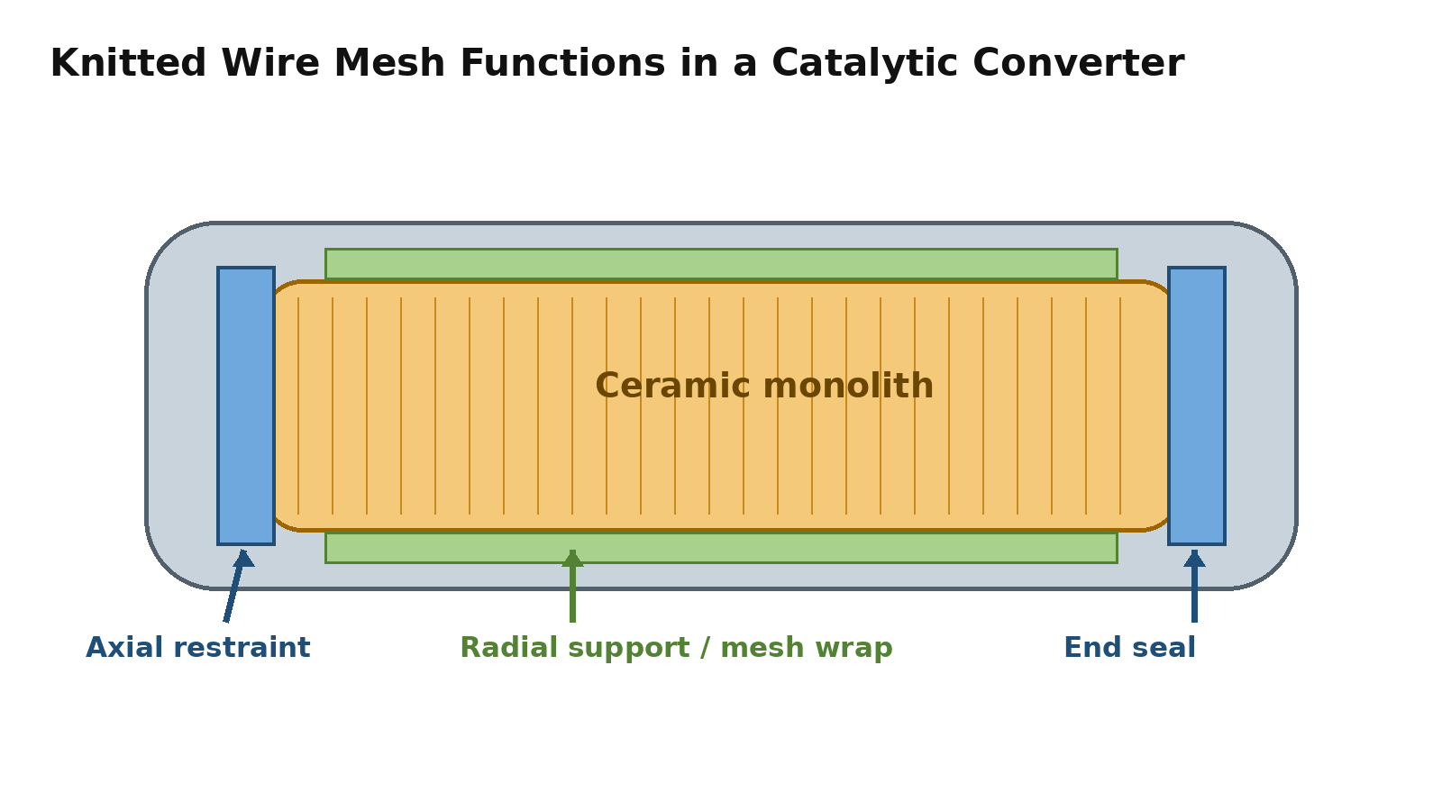
Quick definition: Catalytic converter wire mesh is knitted metal wire used as a compressed support, wrap, end ring or separation component in a specified converter design. Its function may be to restrain radial or axial movement, cushion contact, protect adjacent support material, or help limit gas bypass. The installation position and required mechanical response define the part.
Catalytic converter rattling can be heard during starting, idling, acceleration or travel over a rough road. The sound alone does not identify a failed mesh support: a loose heat shield, hanger, clamp, connection or internal metal part can also rattle, and a ceramic substrate may already be cracked.
This guide takes a manufacturing perspective: how to turn an identified support problem into material, knitting, mass, dimensional and load requirements that can be produced and checked. It applies to designs that actually include knitted wire mesh. Other designs use mounting mats or different retention systems. 3M documents intumescent, non-intumescent and hybrid mat options; a published patent application also describes knitted mesh support structures. These sources establish design alternatives, not a universal specification or a validated service life for the parts shown here.
By Jack Sun. Based on wire mesh manufacturing experience in Anping, Hengshui, Hebei, China.
1. What Does Knitted Mesh Do Inside a Catalytic Converter?
Radial restraint
A compressed mesh layer between the substrate and the housing can provide restraint against sideways movement. The installed compression and contact distribution need to suit the brittle ceramic. Where mesh is combined with a mounting mat, it may serve a more limited role, such as protecting an edge, rather than carrying the entire radial holding load.
Axial restraint and separation
End rings or other specified elements may restrain motion along the exhaust-flow direction. A separation ring between two substrates may maintain spacing or protect adjacent mounting-material edges. Its load direction and interfaces differ from those of a surrounding mesh wrap.
Cushioning and frictional energy dissipation
Wire loops deform and contact one another under compression. Relative contact and sliding can dissipate some mechanical energy. This does not guarantee the elimination of vibration: the response depends on material, wire diameter, loop structure, density, deflection and installation position.
Limiting internal gas bypass
An appropriately designed compressed end component can help reduce flow around the substrate. Knitted mesh remains porous, so an isolated ring should not be described as gas-tight. Bypass performance needs to be checked in the assembled converter. An internal bypass-control component also differs from a gasket intended to prevent external leakage at an exhaust-pipe joint.
2. What Can Rattling, Substrate Movement and Gas Bypass Tell You?
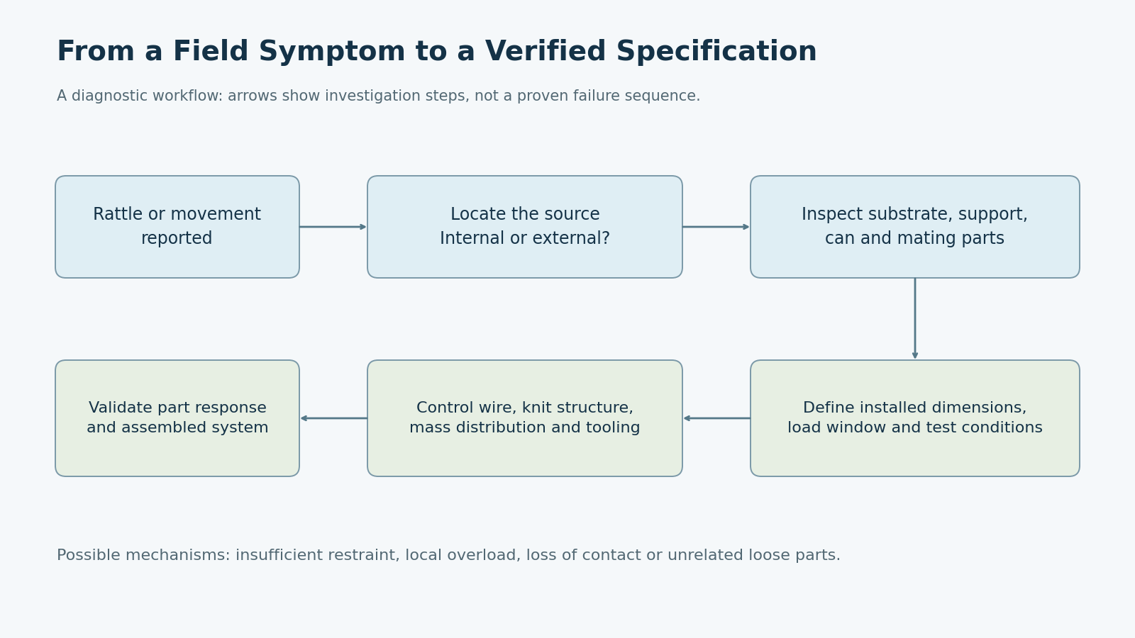
A report of rattling inside a catalytic converter is a starting point for diagnosis. First locate the sound and inspect the substrate, housing, internal restraints and external attachments. Movement can contribute to ceramic damage, while an already fractured substrate can itself become loose; the sound cannot establish the failure order.
Insufficient restraint
Possible contributors include too little installed compression, undersized dimensions, insufficient wire mass, permanent deformation after cycling, uneven circumferential filling, or a mismatch between the support and mating-part tolerances. These possibilities require inspection and measurements rather than a diagnosis from sound alone.
Excessive or uneven compression
More density is not automatically better. Excessive total load or a local hard point can concentrate stress at a ceramic edge. Overlapping preform joints, folds or unequal filling can produce an uneven response even when the finished ring looks round.
Loss of continuous contact
Internal bypass may be associated with discontinuous contact, geometry or position errors, or changes in the mating assembly. It is not the same observation as an external exhaust leak.
| Observed symptom | Mesh-related issue to investigate | Other possibilities to check |
|---|---|---|
| Internal knocking or rattling | Insufficient holding load, incorrect dimensions, loss of response | Cracked substrate or loose internal metal part |
| Axial substrate movement | Insufficient end restraint or incorrect ring position | Misplaced or failed retaining feature |
| Ceramic edge fracture | Local hard point or uneven compression | Ceramic defect or external impact |
| Gas bypass around the substrate | Discontinuous contact or unsuitable component geometry | Housing deformation or assembly gaps |
| Inconsistent batches | Mass, knitting or forming variation | Variation in mating components |
3. Why Does Thermal Cycling Matter?
Passing a room-temperature dimensional check does not prove that a support will retain the required load in service. The housing, substrate and support respond differently to temperature. Differential expansion, changes in stiffness and permanent set can alter contact and installed compression.
Wire loops may rearrange or slip during repeated compression and heating. The resulting changes in free height, recovery and load response matter even when the component remains visually intact. Material selection should therefore address sustained and peak temperature, oxidation, corrosion and condensate exposure, cycling, intended life, and suitability for knitting and forming.
No single temperature rating or service-life claim can be assigned to all knitted mesh rings. Use material data and part and assembly validation appropriate to the actual design.
4. Turning a Support Risk into a Manufacturable Specification
Start with position and load direction
Specify whether the component is a radial support, axial end element, separator or external joint gasket. Identify its mating surfaces and the direction in which it must carry load. A ring shape alone does not define its function.
Specify wire alloy and diameter together with structure
Alloy and wire diameter affect the mechanical response and environmental suitability. They do not uniquely determine performance: different loop sizes, layers, wire masses and installed compression can produce different responses from the same wire.
Control knitting and preform mass
Knitting tension, loop size, pitch and sleeve width affect mass per unit length and preform consistency. The same cut length does not guarantee the same amount of wire. For nominally identical compressed components, wire input mass and its distribution influence apparent density and load response.
Define the apparent-density calculation
For a regular shape, apparent density is component mass divided by an agreed geometric envelope volume. It is not the solid density of the alloy. For flanged, irregular or metal-and-mesh composite components, define the volume boundary and whether metal-skeleton mass is excluded before comparing values. Density is a useful manufacturing-control measure within a consistent method; it cannot replace a load test.
Define dimensions and load at installed deflection
Inside diameter, outside diameter, free height and geometric tolerances determine fit. The load–displacement relationship determines how the component responds when compressed into the assembly. A drawing or sample without material, mass, installed compression and target-load information may permit reproduction of the outline without reproduction of the original mechanical behavior.
5. How Are Knitted Wire Mesh Exhaust Components Manufactured?
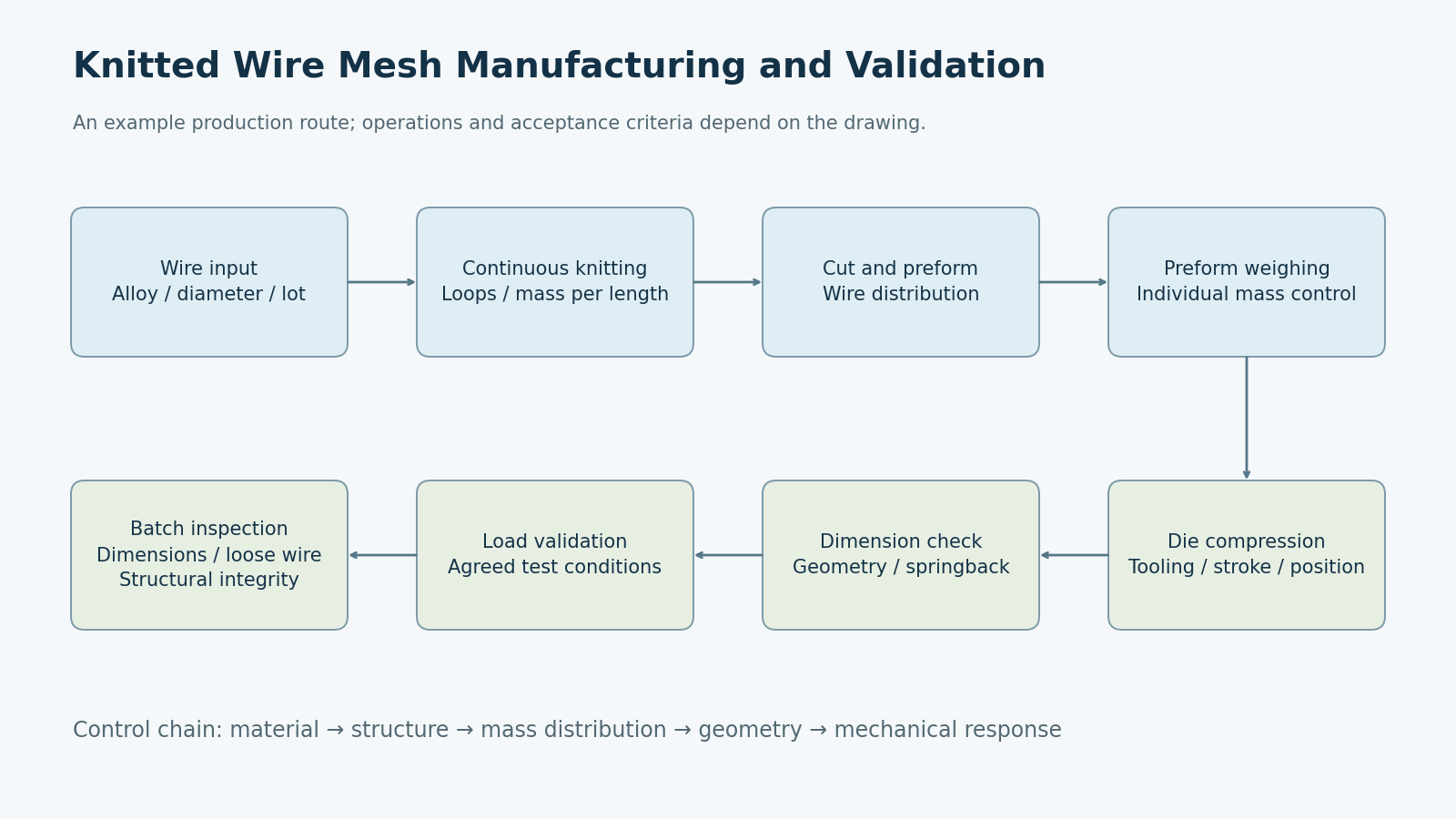
Wire input and identification
Confirm alloy, wire diameter, surface condition and batch identity before production. Material substitutions or diameter changes propagate through knitting, preforming and die compression.
Continuous knitting
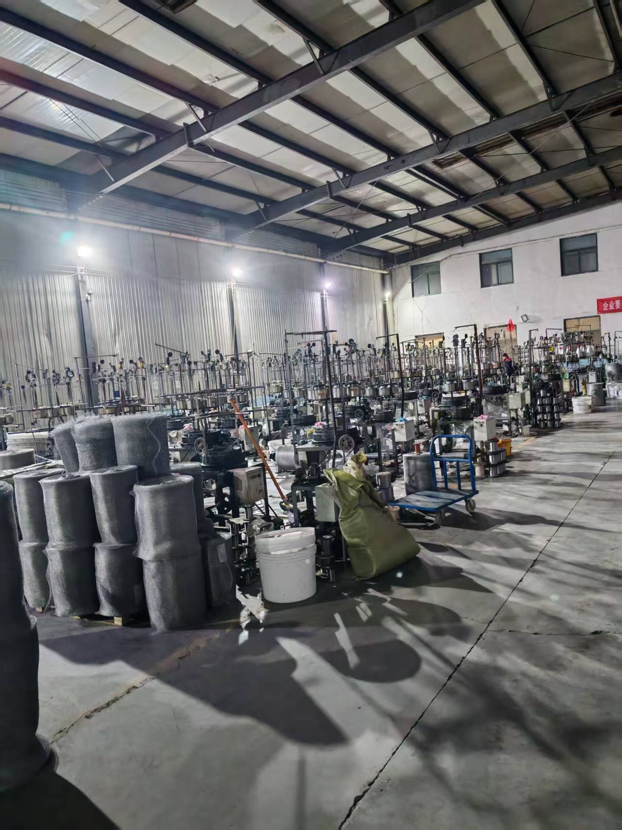
The machine forms a continuous mesh sleeve. This step establishes the basic loop structure and mass per unit length. Local tight or loose knitting can later become variation in mass distribution and compressed response.
Cutting and preforming
The sleeve is cut and rolled, folded or wound into a preform appropriate to the component. The objective is controlled wire distribution in the die, including the location of overlaps and joints.
Preform weighing
Check individual input mass against the agreed production window. Weighing provides information that cut length alone cannot provide when sleeve mass per unit length varies.
Die compression
Tool geometry, clearance, stroke, forming position, equipment repeatability and material recovery influence the finished geometry. A composite component also requires control of the relative position of its metal skeleton and mesh filling.
Demolding and checks
Inspect dimensions, mass, roundness, burrs, loose wires, missing filling and structural integrity as applicable. Components that carry support or cushioning loads may also need agreed load–displacement checks.
6. Which Production Details Cause Variation?
Mass per unit length: a stable cut length cannot compensate for an unstable knitted sleeve. Use preform or finished-component mass checks alongside length control.
Preform distribution: concentrated folds or joints can become local high-density areas. A circular exterior does not establish an even circumferential load.
Tool condition and forming position: wear and positioning variation can change height, edge geometry and repeatability. Tool maintenance needs to follow the component’s critical dimensions and process requirements.
Metal-skeleton location: eccentric positioning, changed filling areas or inconsistent pressing positions can alter effective compression area and local stiffness in a composite part.
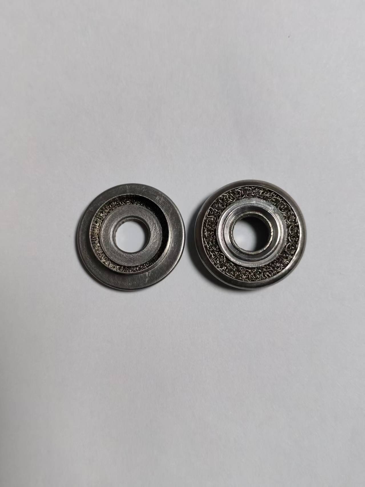
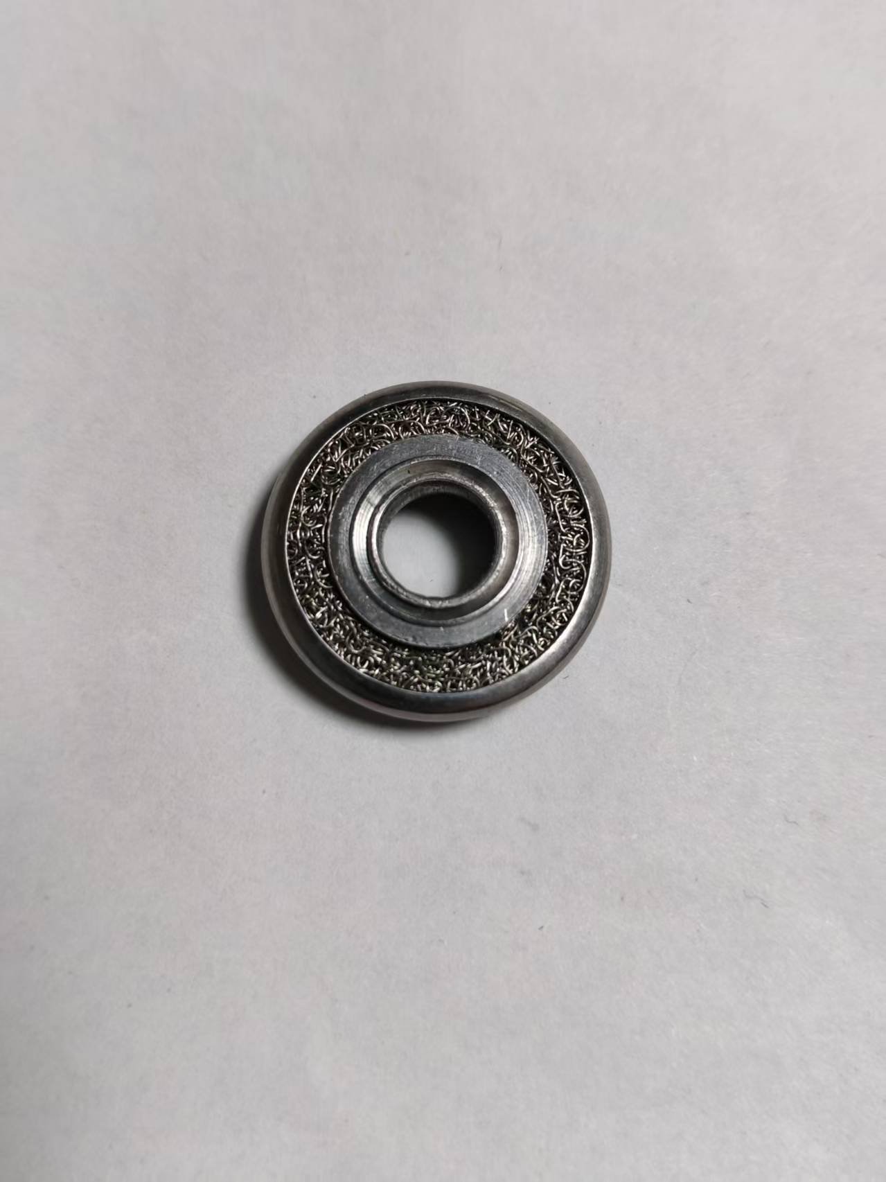
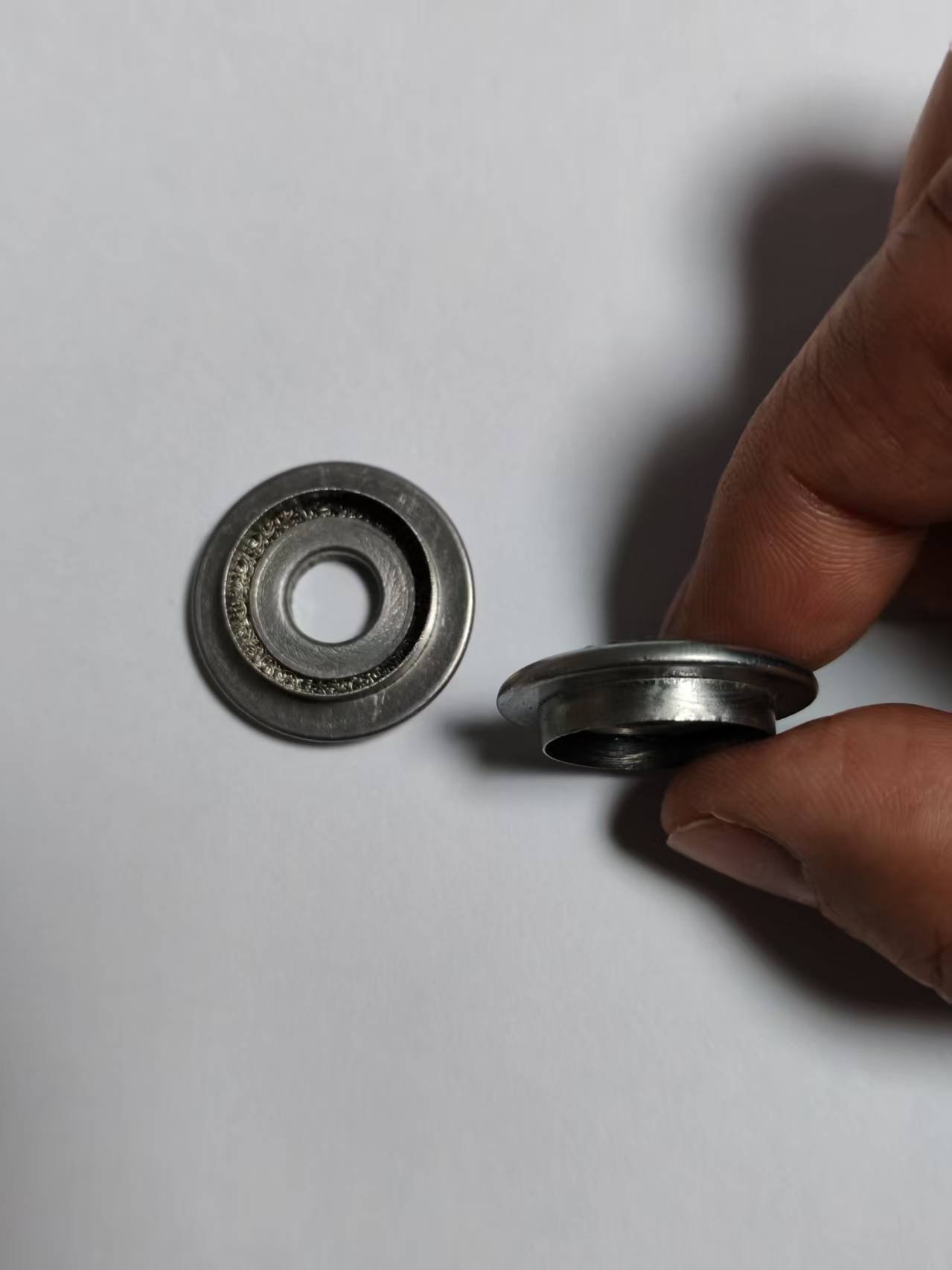
Dimensions without load verification: different materials, wire diameters, masses and internal structures can be pressed into a similar outline. Dimensional conformity alone does not establish the specified support force.
7. How Should Support-Ring Quality Be Checked?
Material, wire diameter and traceability
Check incoming material and batch identity using the documentation or testing agreed for the project. Confirm wire diameter to prevent an unnoticed raw-material change from becoming a change in response.
Individual mass and distribution
Record individual values and batch spread where required. A satisfactory average can conceal unacceptable variation among components.
Dimensions and condition
Depending on the structure, inspect inside and outside diameter, free height, roundness, flatness, flange and skeleton position, and the permitted condition of burrs and loose wires.
Load–displacement tests
Agree compression direction, initial contact reference, compression speed, target displacement, dwell time, cycle count, temperature and sample preconditioning. Comparisons between suppliers or batches are meaningful only when their test conditions are comparable.
Thermal cycling and durability
Where service conditions require it, compare free height, permanent set, load at the target displacement, recovery and loose-wire condition before and after the agreed cycles. A single room-temperature compression does not cover every service risk. Part testing controls manufacturing consistency; the system designer must also validate the assembled converter under representative conditions.
8. Support Rings, End Seals and Exhaust Mesh Gaskets
These components can share knitted wire material and a similar ring shape while serving different functions. Confirm the application before transferring specifications between them.
| Part type | Main function | Main loading | Manufacturing focus |
|---|---|---|---|
| Converter support component | Restrain or cushion substrate motion | Radial or axial compression | Load response, density and dimensional uniformity |
| End sealing component | Help limit gas bypass around the substrate | Axial contact pressure | Continuous contact, density and position; assembly bypass test |
| Separation ring | Maintain substrate spacing or protect mounting-material edges | Axial compression and vibration | Thickness, recovery and shape retention |
| Exhaust mesh gasket | Control external leakage at a pipe connection | Clamping, vibration and thermal cycling | Sealing interface, material and installed dimensions |
| Vibration-isolation component | Dissipate mechanical vibration | Direction-specific cyclic loads | Stiffness, damping and fatigue behavior |
| Metal-and-mesh composite | Support, seal or damp according to its design | Depends on the structure | Skeleton position, filling distribution and assembly integrity |
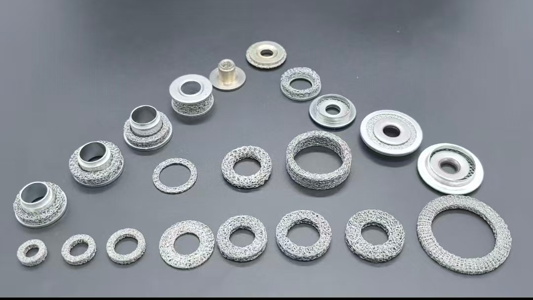
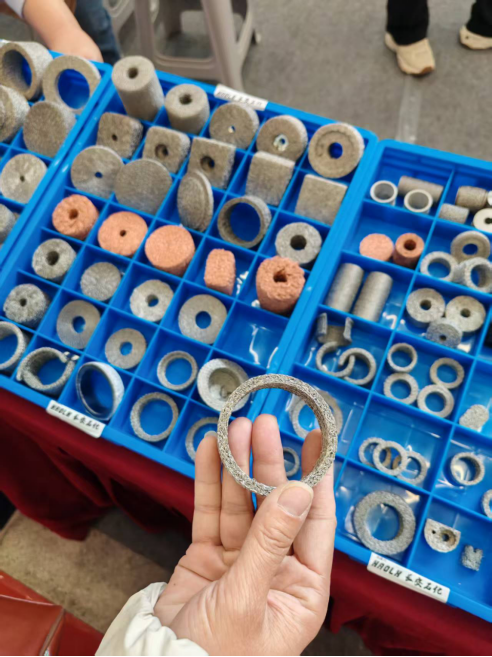
For available formed-part configurations, see compressed knitted components. The knitted mesh density and porosity calculator helps organize mass and agreed envelope-volume data; the metal cushion damper guide explains preload, displacement and mechanical verification. Neither density nor product shape establishes a converter support load.
9. What Information Is Needed for Sample Development?
- Installation position, intended function and load direction
- Wire alloy and diameter
- Free dimensions, tolerances and installed compression dimensions
- Individual mass or an agreed density calculation
- Sustained and peak temperature, oxidation and corrosion exposure
- Target load–displacement data and agreed test conditions
- Thermal-cycle or durability requirements
- Expected quantity and batch-consistency requirements
A sample helps identify geometry, material, wire diameter, approximate knitting structure and forming method. Its appearance and dimensions alone may not reveal the original support-load requirements. When design information is incomplete, use measurement, material and diameter identification, mass and density analysis, trial production, load testing and assembly validation before moving into serial production.
10. Frequently Asked Questions
What causes a catalytic converter to rattle?
Possible causes include a cracked or loose ceramic substrate, insufficient internal restraint, a loose internal metal part, an external heat shield or an exhaust attachment. Sound alone cannot identify a mesh-support failure. Locate the source and inspect the assembly.
Can knitted wire mesh prevent catalyst substrate movement?
In a design that includes a mesh support, wrap, end element or separator, an appropriately designed and compressed component can restrain radial or axial movement. The result depends on its role, material, installed deflection, load distribution and behavior after thermal exposure.
Is higher wire mesh density always better?
No. Too little restraint can allow movement, while excessive or uneven compression can create high load or local hard points. Specify an appropriate load window at the installed displacement and check the relevant distribution.
What is the difference between a support ring and an exhaust gasket?
A support restrains an internal substrate. An end sealing element helps limit internal bypass. An exhaust connection gasket controls external leakage at a pipe joint. Similar materials do not make their installation and validation requirements interchangeable.
Can a mesh component be reproduced from a sample?
A sample can guide geometry, material, wire, mass and structure analysis. Matching its outline does not guarantee the same mechanical response. Installed compression, target load and operating conditions are also needed.
Which parameters should be checked for each batch?
The agreed plan may include material identity, wire diameter, individual mass, diameters, height, geometric condition, appearance and load–displacement data. Thermal cycling or repeated compression may be required for a particular project.
Are knitted mesh supports used in every catalytic converter?
No. Converter designs can use mounting mats, mesh, a combination, or other retention arrangements. Apply this guide only where the specified design contains knitted mesh components.
From an Observed Symptom to a Verified Component
A catalytic converter rattle is an observation, not a production specification. The manufacturing task is to connect the identified motion, restraint, local-load or bypass issue with material, wire, knitting, preform mass, density, dimensions and load requirements. An acceptable outline alone does not prove stable operation in the assembled system.
For development of a support ring, end sealing element, separator or metal-and-mesh composite, provide the drawing or sample together with assembly dimensions and load requirements. Contact our engineers to discuss a component that can be manufactured and validated against those requirements.
Technical Background
- US20040219076A1 — Catalytic converter support system: a published example of knitted wire mesh support architecture, not a universal product specification.
- 3M mounting mats for OEM and Tier suppliers: background on intumescent, non-intumescent and hybrid mounting-mat alternatives.