Quick definition: Polymer melt filtration uses a filtration medium to retain particulate contamination in a flowing melt. Woven wire mesh can act as the retention layer, with supporting mesh and equipment support. Selection requires the contaminant, pore structure, melt-flow conditions and installation arrangement; a mesh count or micron label does not describe the complete process.
If a product develops black specks, particles or film defects, identify their origin before changing screens. The objective is a workable balance of retention, differential pressure and structural stability for the production line. Smaller openings alone do not establish a better result.
This guide focuses on how screen layers work and how to interpret filtration results. Mesh dimensions, materials and delivery requirements belong in the purchase specification. Screen changers and extruders are equipment systems; supplying mesh does not imply supplying those machines.
Contents
- Identify the melt and contaminants
- Separate mesh count, openings and micron ratings
- Assign a role to each screen layer
- Interpret pressure by location and operating stage
- Investigate downstream defects
- Prepare manufacturing information
- Frequently asked questions
Identify the Melt and the Contaminants
The polymer is the continuous phase that should pass through the medium; contamination is what should remain behind. Different contaminants behave differently at processing temperature and cannot all be treated as rigid spherical particles.
Pachner and colleagues’ research on initial pressure drop in melt filtration discusses recycled-polymer contamination such as paper, metal, glass, and unmelted or degraded polymer. Retention and initial resistance need to be considered together when selecting a filtration system.
| Contaminant | First establish | Implication |
|---|---|---|
| Rigid solid | Size distribution, shape and concentration | Compare with pore structure, then validate retention |
| Other polymer or deformable particle | Softening, deformation or melting at processing temperature | Room-temperature size does not directly establish hot retention |
| Gel or degradation product | Origin, form and whether it develops after the screen | Increasing mesh count may not resolve the product defect |
“Recycled feedstock” is not a complete contaminant description. Different feed batches may produce different operating curves even with the same polymer and nominal rating. Keep feed-batch identification, upstream and downstream samples and product-defect records so changes can be compared.
Separate Mesh Count, Pore Structure and Micron Labels
For square woven mesh, record count, wire diameter and clear opening together. Different wire diameters at the same count produce different openings; count alone cannot specify the geometry. Our Wire Mesh Size Calculator supports preliminary square-mesh comparison.
Dutch weave requires warp and weft counts, both wire diameters, the specific weave and the test basis of its filtration rating. Its flow passages do not follow the ordinary square-mesh conversion, and front-view photographs cannot reliably determine its filtration performance.
A micron value should state whether it is a geometric opening or a filtration rating determined by a particular method. For a nominal rating, confirm the definition and test conditions. A room-temperature screening opening is not automatically a retention guarantee for all particles in a hot melt.
Validate melt filtration with the target polymer and representative contaminants. Alongside samples or defect inspection, record flow, temperature, screen structure and differential pressure. This allows changes to be traced to a specific factor. The rating and efficiency guide explains why a size label alone is insufficient.
Assign a Defined Role to Every Screen Layer
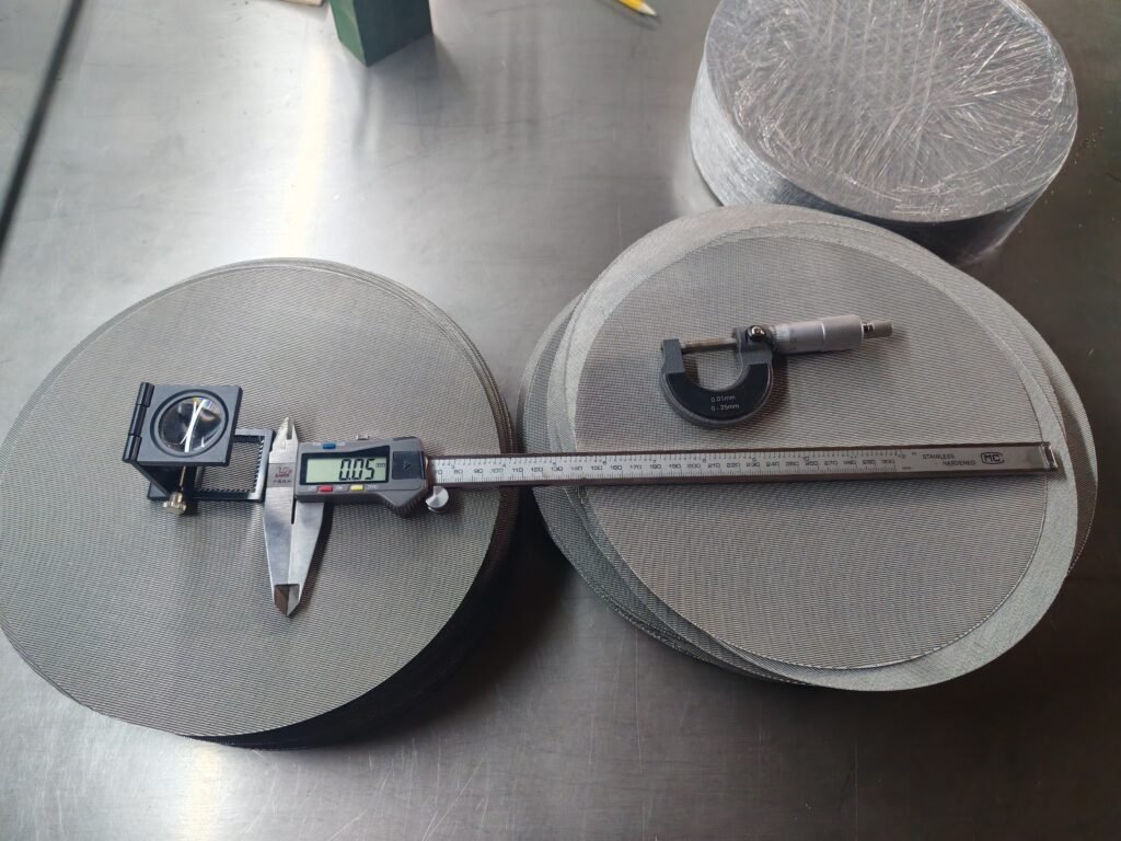
For manufactured discs and packs, review our extruder screen product options alongside the equipment drawing. The open-area and pressure-drop guide explains geometry and assembly effects; it does not predict molten-polymer pressure loss from mesh count alone.
A screen pack may contain a retention layer and support layers. List their roles instead of treating “multiple layers” as a performance specification. The fine layer defines the target pore structure; supporting mesh helps control deformation; the equipment support plate or breaker plate provides installation and load support. Contact, supported area and direction should agree with the equipment drawing.
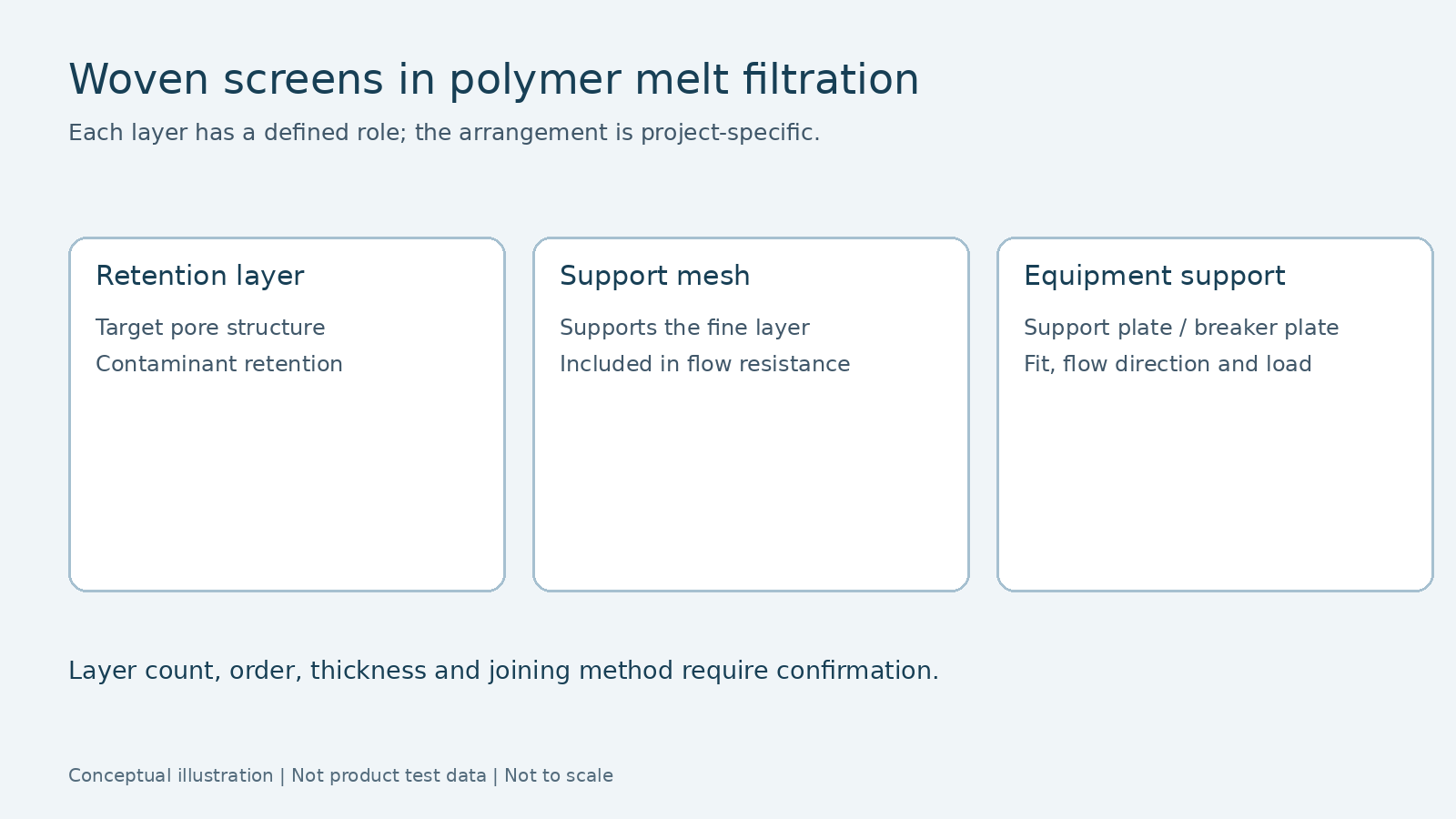
Koller, Paulik and Burgstaller compared assembled and fused screens in polypropylene melt experiments. Contaminant deformability and screen structure affected retention; support and screen deformation were also relevant. Those specific materials and equipment conditions do not establish a universally superior arrangement.
For manufacturing review, list each layer’s grade, weave, count or pore structure, wire diameter, outline, joining method and upstream/downstream orientation. An added layer should have an explicit retention, support or protection role, with overall thickness and installation clearance rechecked.
Multiple layers do not necessarily mean a sintered structure. Loose stacking, spot welding, edge binding and sintered bonding are different joining methods and must be documented separately.
Interpret Pressure by Measurement Location and Operating Stage
Distinguish equipment pressure from differential pressure across the filtration section. An upstream reading alone is not screen differential pressure: the downstream pressure and intervening flow passages must also be known.
Pachner and colleagues distinguish flow-channel loss from filter-medium loss in a model of initial, isothermal filtration with a non-Newtonian melt. The clean screen’s initial resistance therefore needs to be separated from changes caused by accumulating contamination.
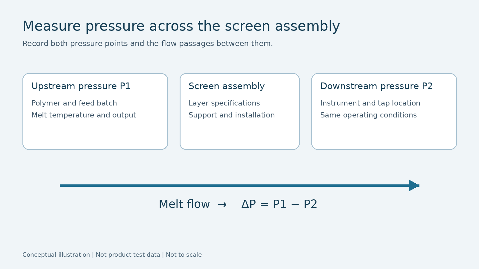
| Observation | Check first | Record |
|---|---|---|
| High pressure after installing a new screen | Feedstock, temperature, output, layers and installation versus the baseline | Initial performance under comparable conditions |
| Progressive pressure increase | Changes in contamination, output or temperature | Trend with upstream/downstream samples |
| Sudden pressure decrease or fluctuation | Flow, temperature, instrumentation and assembly integrity | Evidence of bypass or damage |
Bennett and colleagues’ 2024 modeling and experimental study examines initial resistance through multilayer woven screens. Layer configuration needs structure-specific analysis. Equal open-area percentages cannot replace flow validation, and clean-screen results cannot predict the full fouling cycle.
For engineering comparisons, hold polymer grade, feed condition, output or flow, actual melt temperature and equipment configuration as consistent as practicable. Record simultaneous changes so all differences are not attributed to mesh. Pressure can also change through operating conditions or measurement faults.
Determine changeover criteria from equipment limits, support and joining structure, and project validation. This article specifies no universal differential pressure or service interval. Experimental stopping pressures are not field settings. The liquid Darcy examples in our sintered-mesh pressure-drop guide should not be applied directly to non-Newtonian polymer melts.
Investigate Defects That Remain After Filtration
First check whether the contaminant is suitable for the intended mechanical filtration, then examine the screen and installation. Downstream particles do not automatically prove that mesh count is too low, and lower pressure does not prove restored filtration.
Link three sets of records: upstream/downstream samples, the removed assembly’s mesh and edge/joint condition, and temperature, output and pressure trends from the same period. Together they provide a stronger basis for diagnosis than a single photograph.
For suspected bypass, inspect edge fit, cut-piece dimensions, layer restraint and orientation. For deformation or rupture, examine support contact, unsupported span and pressure history. Use inspection evidence to identify causes; appearance alone supplies a clue.
For deformable contamination, smaller nominal openings can also alter resistance and operating conditions. Koller and colleagues’ experiments indicate that contaminant rigidity, loading and screen structure belong in the evaluation. Validate changes with representative samples rather than inferring performance from the material name.
Reuse after cleaning also requires structural and performance checks. A visually clean surface does not establish restored pore structure, attachment integrity or retention. Reusability depends on contamination, material, joining method and a verifiable cleaning procedure.
Prepare Information the Manufacturer Can Use
For a new project, start with polymer, contamination and production goals. For an existing-equipment replacement, supply drawings and installation requirements. A sample can help reconstruct missing geometry, but identify deformation and wear.
| Information group | Provide | Purpose |
|---|---|---|
| Melt and contamination | Polymer, temperature, feed batch and target contaminants | Define the filtration task |
| Operation and equipment | Output or flow, pressure points, screen changer and support | Review conditions and installation boundary |
| Mesh and finished form | Each layer’s specification, material, outline, joining and direction | Produce a manufacturable assembly record |
| Validation and delivery | Sample tests, appearance, dimensions, traceability and acceptance | Agree verification criteria |
We review these records from the mesh and finished-component manufacturing perspective. Outline, thickness, layer specifications and restraint guide cutting and assembly. Final process performance requires verification by the equipment supplier or user under the relevant melt conditions. General purchasing parameters are covered in the wire mesh specification guide.
Frequently Asked Questions
Can screens with the same mesh count be interchanged?
Also compare wire diameter, weave, alloy, layers, overall thickness and installation. Equal count does not establish equal geometry or operation.
Can supporting mesh change pressure drop?
Yes, it lies in the flow path and needs assessment with the retention layer. Recheck installation and flow conditions after adding support.
Can a pressure curve establish filtration efficiency?
No. It reflects resistance and operating changes. Retention also needs upstream/downstream samples or product-inspection evidence.
Selection Summary
Define the contamination, then the pore structure, support and assembly. Compare initial performance and subsequent changes under stated conditions. This turns a preference for finer mesh into a filtration choice that can be verified.
Author: Jack Sun has long-term experience in woven metal mesh and industrial filter-element manufacturing. Filtalloy is based in Anping, Hengshui, Hebei, China. We discuss mesh and finished structures from operating requirements, drawings or samples; final performance is project-specific.
Technical references: Pachner et al., Polymer Engineering & Science (2019), DOI 10.1002/pen.25088; Koller et al., SPE Polymers (2022), DOI 10.1002/pls2.10061; Bennett et al., Chemical Engineering Research and Design (2024), DOI 10.1016/j.cherd.2024.08.002. Links appear alongside the relevant discussion; no paper figures or data tables are reproduced.
Related resources: Woven Wire Mesh Applications · Woven Mesh Products · Plastic Industry Filtration