By Jack Sun · Updated October 22, 2026
Multilayer sintered wire mesh combines woven metal meshes of different specifications into a porous filter medium. The filtration layer provides the principal particle-retention structure, while adjacent meshes provide protection, a transition for flow, and mechanical support. Five layers are a common arrangement, but layer count alone does not establish filtration rating, flow resistance or allowable differential pressure.
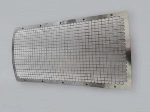
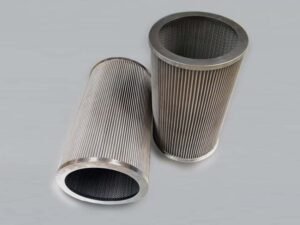
The two faces of a sheet may show different weave patterns. A finished cartridge may also have coarse mesh or a perforated support around it. These visible features help identify component positions; installation direction still depends on the actual layup and element design. Understanding the structure starts with two questions: which layers does the fluid pass through, and how is the filtration layer supported?
Different functions within the laminate
The layers do not all perform the same task. A fine filtration mesh provides the main retention structure. Surrounding meshes help it maintain the required arrangement during processing and service. Sintering bonds suitable contact points so that the meshes work as a laminate. [1]
| Structural function | Role in the medium | What to examine |
|---|---|---|
| Protection | Reduces direct contact, abrasion or handling damage to the filtration layer | Which face is protected and how the outer mesh contacts the fine mesh |
| Filtration | Provides the principal structure for specified particle retention | Weave, wire diameter, pore geometry and rating definition |
| Transition and distribution | Connects fine mesh to coarser support and provides space for flow | Interlayer contacts, passages and resistance |
| Support | Limits deformation of fine mesh or the laminate | Wire diameter, weave, support position and unsupported span |
“Filtration layer” and “support layer” describe structural responsibilities. They do not assign a universal filtration rating to each individual layer. Two support meshes may still differ in wire diameter, weave and contact with adjacent layers.
The filtration layer is not necessarily the outermost visible mesh. Where a protective mesh covers it, the surface pattern belongs to that protective mesh. Its coarse openings do not mean the complete medium retains only particles of that size.
How a common five-layer structure works
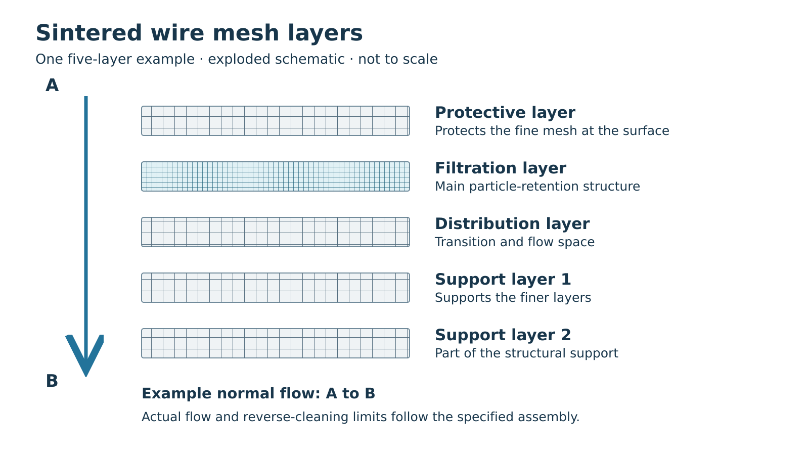
One of our standard five-layer arrangements consists of a protective layer, a filtration layer, a distribution layer and two support meshes. The following example explains their functions. Its layer order and flow arrow are specific to the illustrated arrangement.
Protective and filtration layers
The protective mesh is on the inlet side in this example, reducing the fine mesh’s direct exposure to contact. It can take some contact during sheet handling, assembly or subsequent operations. Sharp tools, excessive local clamping and unsuitable cleaning can still damage the structure, so the fine mesh’s condition remains relevant.
The filtration mesh’s weave and specification establish the retention structure that needs examination. Mesh count, wire diameter and weave are mesh parameters; the final nominal rating and particle-retention performance need their own definitions and test conditions. See the filter micron rating and efficiency guide for these distinctions.
Distribution and support layers
The transition from a fine filtration mesh to coarse support involves both contact geometry and flow. An intermediate distribution or transition layer provides space for flow and a structural transition, rather than relying only on direct contact between the finest and coarsest meshes.
This does not guarantee uniform flow throughout an entire filter. Perforated supports, drainage passages, edge seals and equipment channels also influence flow distribution. Flow space within a material and flow distribution within equipment are related design questions with different boundaries.
The two support meshes help stabilize the laminate. Their contribution depends on weave, wire diameter and bond condition. Following the load path from finer meshes into stronger structures helps explain support, but the supports beneath a plate or inside and outside a cartridge, and the distance between them, also matter.
Variations in layer count and support construction
Changing layer count changes the combination of functions. An added layer may provide protection, transition or support. It does not automatically make filtration finer, or change flow per unit area and allowable differential pressure in proportion to the number of layers.
Arrangements beyond five layers
Our sintered mesh media and filter elements page includes specification tables for five-layer media, other multilayer combinations and perforated-plate composites. Different layer counts serve different functional combinations within the same material family.
An arrangement with fewer layers may combine filtration mesh directly with a suitable support. Another may add protection or an intermediate mesh. Compare the function added or removed, then examine how the resulting thickness, flow and loading meet the requirement. “Two fewer layers” alone cannot establish a numerical reduction in pressure drop.
Primary manufacturer literature also illustrates this variety: BOPP lists five-layer products alongside two- and three-layer laminates for different tasks. [2] These examples demonstrate possible arrangements; another manufacturer’s specifications and performance values do not become specifications for our products.
Bonded perforated plates and separate support cages
A perforated plate can provide substantial support, but its connection to the meshes needs to be defined. A composite sintered together with its plate differs structurally from a separate perforated support tube added during element assembly.
In the first case, the plate is part of the laminate being evaluated. In the second, it is an adjacent component of the finished element. Both can affect available flow space and loading; the visible hole size alone cannot establish the element’s filtration rating.
Nor does a perforated support make its entire geometric area available for direct flow. Holes, solid ligaments and peripheral fixing regions create different local flow and support conditions. When comparing flow or pressure-drop data, identify whether the specimen was a sheet or a complete element with supports and connections. See sintered wire mesh differential pressure for calculations and the use of reference data.
Normal filtration and backwash direction
A flow designation should identify the inlet face, the higher-pressure side during normal filtration, and whether cleaning involves reverse flow. These conditions affect how the filtration layer and its supports work together.
Confirm normal direction from the actual construction
In Figure 1, normal flow enters face A, crosses the protective and filtration layers, and leaves through the distribution and support meshes at face B. The arrow describes that construction; it does not apply automatically to every sheet with a coarse face and a fine face.
For another sheet, use its structural marking, supply drawing or confirmed installation requirement. Judging direction only by which face looks brighter or coarser can confuse surface appearance with layer function.
For a cartridge, sheet faces A and B must also be mapped to the inside and outside of the cylinder. With specified outside-to-inside filtration, the inlet face belongs on the outside. With inside-to-outside flow, that relationship reverses. The finished marking or drawing should preserve this relationship after rolling and end assembly.
Reverse cleaning changes the load path
Backwashing sends fluid from the normal downstream side toward the upstream side to help remove contamination. In Figure 1, that means B to A. The ability to pass fluid in reverse and the allowable backwashing conditions of a finished element require separate confirmation.
Reversing differential pressure changes the loads on the fine mesh, interlayer bonds and adjacent supports. A support arrangement effective during normal filtration does not establish equal capability in the opposite direction. Backwashing may also involve short pulses, repeated cycles and end loads that need assessment with the complete construction.
Normal differential-pressure limits and backwashing conditions therefore need their respective directions and structural boundaries. Differential pressure is the pressure difference across the filter; the equipment’s total internal pressure cannot substitute for it. There is no single backwash pressure or cycle count established here for every sintered mesh.
From sheet structure to a complete filter element
The sheet layup is one part of an element. Its support, end connections and any route allowing fluid to bypass the filtration layer also affect the result.
For example, rolling a sheet with identified A and B faces into an outside-to-inside cartridge requires face A to remain outside. The internal support, longitudinal seam and end connections then need consideration. Rolling preserves the layer names while changing shape and interaction with adjacent parts.
If a joint provides a path around the filtration layer, the sheet’s rating does not describe that bypass. See welding joints in wire mesh filters for the relationship between connection strength and the filtration boundary.
| Object being examined | Structure to understand | Relevant information |
|---|---|---|
| Sintered mesh sheet | Layup, filtration-layer position, thickness and specified direction | Structure drawing and material specification |
| Cut or formed part | Layer orientation, edges, curvature and support contact | Part drawing and processing requirements |
| Complete cartridge or plate | Supports, joints, seals and the complete filtration path | Assembly drawing and finished-component validation |
An existing drawing, specification or sample is a useful starting point for supply. Defined layer order, thickness, dimensions and direction can guide manufacturing discussions directly. Only gaps affecting the current decision need clarification. Assessing the performance of a new construction may require additional operating conditions and validation requirements.
Frequently asked questions
Can the protective mesh simply be omitted?
Its removal depends on its actual responsibility. If it protects fine mesh or contributes to processing contact or structural fit, those tasks still need to be fulfilled after removal. Evaluate the revised arrangement before deciding whether fewer layers are suitable.
Can two constructions of equal thickness replace one another?
Equal thickness establishes one shared geometric dimension. Filtration mesh, support mesh, interlayer bonding and finished-element supports may still differ. Keep the required filtration, flow and installation conditions in view when assessing a replacement.
Are the coarse holes outside a finished element its filtration rating?
Not necessarily. They may belong to protective mesh or a support component, with the filtration layer inside. Identify the structural role first, then consult the complete medium’s rating and test definition.
Relating layer functions to flow and support helps identify what needs checking in a five-layer sheet, another laminate or a supported cartridge. For the manufacturing steps that produce these structures, see how sintered wire mesh is made.
Technical sources
GKD — Sintered Mesh. General principles of lamination and bonding; accessed October 22, 2026.
BOPP — Sintered Wire Cloth. Five-layer and two-/three-layer examples; file identifier 2015. Product performance values are not transferred to our materials.
About the author: Jack Sun has long worked in metal wire mesh weaving and industrial filter-element manufacturing. Filtalloy is based in Anping, Hengshui, Hebei, China, known for wire mesh manufacturing.