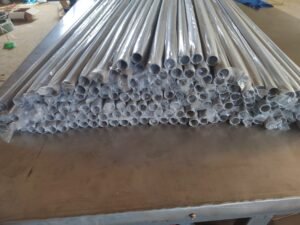
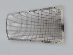
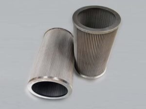
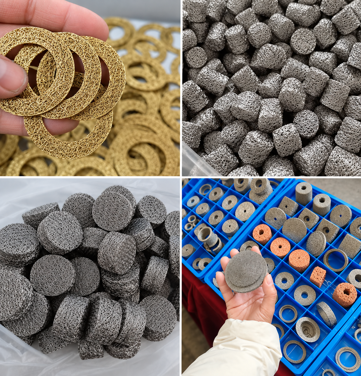
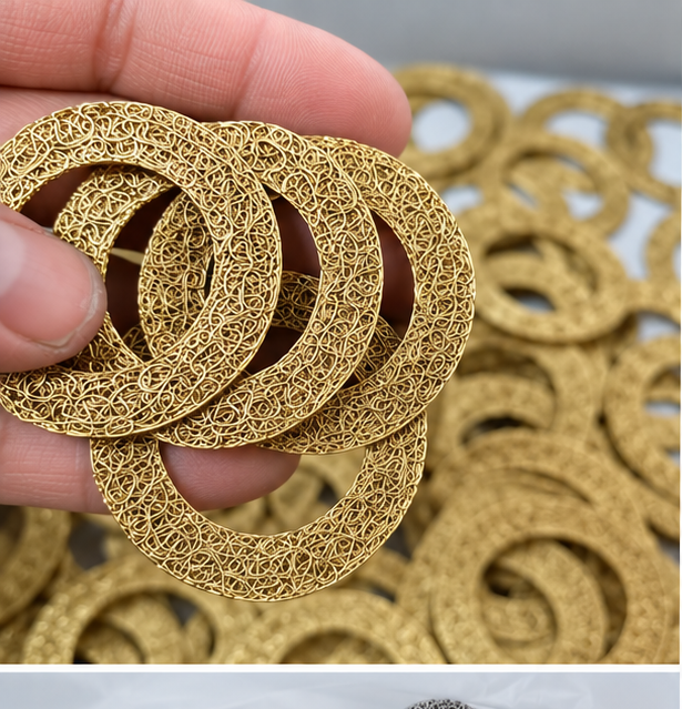
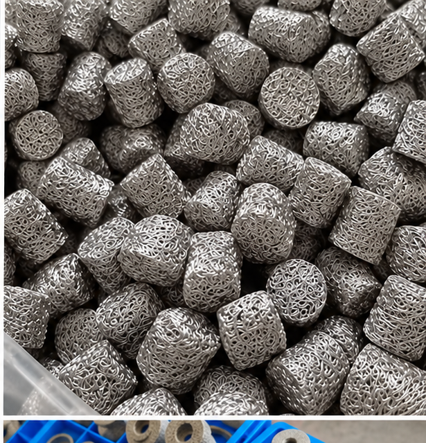
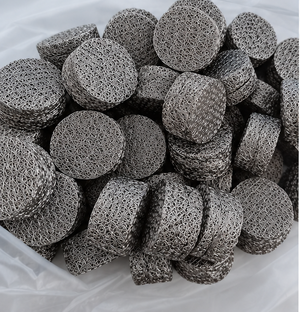
Compressed knitted wire mesh is a three-dimensional porous metal component made by rolling, folding or preforming knitted wire mesh and compressing it in a die. Its specification combines material, wire diameter, knitted structure, mass, density, dimensions and operating conditions.
A customer may send a drawing with only an outside diameter, inside diameter and height. Those dimensions define the space a part occupies, but they do not tell us how much wire it contains or how the internal network should behave.
Two parts with identical dimensions can have different wire diameters, weights and compression states. Start with what the component must do, then translate that function into a manufacturable structure.
By Jack Sun. Our company is based in Anping County, Hengshui, Hebei, China, a center of the wire mesh industry. Jack Sun has long worked in wire mesh weaving and industrial filter manufacturing. This guide explains how manufacturing and purchasing requirements connect; product performance must be verified for the intended conditions.
1. What Is Knitted Wire Mesh?
Knitted wire mesh uses continuous wire to form interconnected loops. Woven wire mesh uses crossing warp and weft wires to create a more regular two-dimensional aperture. The square-mesh count and aperture formula cannot be transferred to knitted mesh.
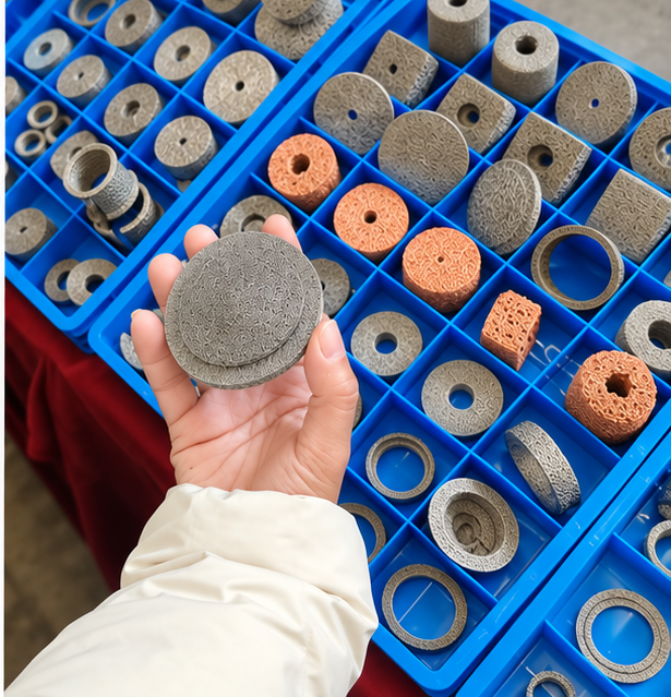
Knitting produces a flexible mesh sleeve or strip. Rolling, folding and die compression turn it into rings, discs, cylinders, sleeves or custom parts. The final behavior comes from the wire material and the three-dimensional contact network, rather than the outside shape alone.
2. Start with the Application
Define the function before selecting a target density. Filtration, gas–liquid separation, damping, sealing, noise control and electromagnetic shielding need different acceptance criteria.
| Application | Priority inputs | Verification |
|---|---|---|
| Filtration | Fluid, contaminants, flow and allowable pressure drop | Efficiency and pressure drop under defined conditions |
| Mist removal | Droplet distribution, gas velocity and drainage | Separation, wet pressure drop and re-entrainment |
| Damping | Load, displacement, excitation and installation | Force–displacement behavior and dynamic response |
| Sealing | Gap, compression, medium and temperature | Installed sealing performance |
| EMI/RFI shielding | Conductivity, contact and frequency range | Complete assembly shielding performance |
3. Material Selection
Select a specific grade against the medium, continuous and peak temperatures, corrosion conditions, mechanical load and cleaning process. A material name alone does not establish a universal temperature limit.
| Material family | Selection considerations |
|---|---|
| 304 stainless steel | A candidate for many general industrial environments; check actual corrosion conditions. |
| 316L stainless steel | A candidate when corrosion requirements increase; suitability remains dependent on medium and temperature. |
| Nickel-based alloys, including Inconel | Specify the exact grade, atmosphere and continuous/peak exposure. |
| Monel | Confirm the exact alloy against the specific corrosive medium. |
| Copper and copper alloys | Consider conductivity together with environmental and mechanical requirements. |
4. Wire Diameter and Knitted Structure
Wire diameter affects the quantity of wire per volume, internal surface area, contact behavior and possible flow paths. Fine wire does not automatically give a better filtration rating; coarse wire does not automatically give lower pressure drop.
Define wire diameter together with loop structure, mesh width, preforming route and compression. A change in one variable can require adjustment of the others.
5. Calculate Bulk Density
For a component with a reliably determined geometric volume, bulk density is ρb = m / V. It is the mass of wire divided by the component envelope volume, including internal voids and excluding macroscopic openings such as a central through-hole. Exclude separate frames and inserts from the wire mass.
For a regular ring, V = π/4 × (Do² − Di²) × H. Use compatible units: dimensions in cm give volume in cm³; mass in g gives bulk density in g/cm³. Record whether dimensions represent the free or installed state.
Higher density is not automatically better. Adding wire to the same envelope changes contacts, stiffness, flow resistance and capture behavior. Compare density only with a common state and test basis.
6. Porosity and Installation Compression
For a single-metal component without other fillers, estimated porosity is ε = 1 − m / (ρs × V), where ρs is the solid metal density. Use compatible mass, density and volume units. ε is a dimensionless fraction; multiply by 100% to express a percentage.
Estimated porosity is not pore size or filtration rating. The calculation describes total void fraction and does not distinguish connected from closed voids or show the pore-size distribution. Mixed materials, coatings, inserts or uncertain volumes require a different calculation basis.
A part may be compressed again after installation. That changes the volume, wire contacts and flow paths. Specify installed dimensions whenever pressure drop, stiffness or sealing depends on compression. Manufacturing compression and installation compression must have separate definitions.
Height example: 70% remaining means a 30% reduction. If free height is 20 mm and installed height is 14 mm, the remaining height is 14/20 = 70%, while installation compression is (20-14)/20 = 30%. These are two descriptions of the same height change using the same reference.
The numbers illustrate arithmetic, not a recommended compression. The manufacturing preform height needs a separate reference. Record the force in N at the defined height and test condition; height percentage alone cannot supply it.
7. Dimensions, Shapes and Tolerances
Rings require OD, ID and height; rectangular parts require length, width and height. Include part weight, critical tolerances, compression direction and any steps or holes. Dimensions and density are linked: compressing the same wire mass into a smaller envelope changes the structure.
Separate fit-critical dimensions from performance-critical parameters. An outside diameter may control assembly, while height controls installation compression and weight controls the amount of wire.
8. Common Selection Mistakes
- Providing only OD × ID × H without wire diameter, weight or functional requirements.
- Specifying ‘high density’ without a load, flow or acceptance target.
- Using mesh count as a filtration rating for a compressed three-dimensional network.
- Ignoring additional axial or radial compression inside the housing.
- Applying a filtration test result to a damping or shielding application.
- Copying the dimensions of a worn, permanently compressed old part as if they were its original design.
9. Specification Checklist and Sample Development
Provide the application, medium, temperature, quantity, material, dimensions, tolerances and drawing or sample. Add wire diameter, part weight or density if known. Functional parts also need flow/pressure data, loads or shielding targets as applicable.
Unknown parameters do not need to be invented. Actual operating conditions are more useful than an unsupported target density. A sample can reveal dimensions, weight, wire diameter and structural features, but material and original condition may require additional investigation.
Use a development sequence of sample analysis → prototype → application test → adjustment → production. Reverse engineering establishes an initial specification; it does not guarantee complete recovery of a used part’s original design.
10. Frequently Asked Questions
Is higher density better for filtration?
Not necessarily. Density affects wire contacts and flow paths and may increase flow resistance. Validate efficiency and pressure drop with the intended fluid and contaminants.
Can knitted wire mesh be used at high temperature?
Suitable alloys can be considered, but the limit depends on exact grade, atmosphere, corrosion, load and exposure duration. The knitted structure alone does not define a temperature rating.
Can a component be customized from a sample?
Yes, a sample can support analysis and prototyping. Provide installation dimensions and operating conditions because wear or permanent compression may have changed the sample.
Does estimated porosity indicate a micron rating?
No. Total void fraction does not establish individual flow-path dimensions or a tested retention efficiency.
11. Conclusion and Related Resources
A useful compressed knitted wire mesh specification connects application, material, wire diameter, knitted structure, mass/density, dimensions, installation state and validation. Freeze those parameters and the inspection method after the prototype has passed the agreed checks.
Explore compressed knitted components and the knitted mesh density and porosity calculator. For friction, stiffness and hysteresis in metal cushions, see Frequency-Adaptable Tuned Mass Damper Using Metal Cushions; its experimental results are not ratings for every knitted mesh product.
Discuss Your Compressed Knitted Mesh Requirements
- Application-based customization: provide operating conditions, installation space and functional targets to establish an initial specification and prototype.
- Drawing-based customization: provide materials, dimensions, tolerances, connections and agreed acceptance requirements.
- Sample-based customization: provide the existing part and mating components; evaluate wear, contamination and permanent deformation before confirming a replacement.