A knitted wire mesh filter uses interconnected wire loops as its principal media. Rolls, framed panels, compressed components and custom shapes combine different manufacturing and installation requirements; filtration behavior needs a defined test basis.
Customers often know the form they need: a mesh roll, framed panel, compressed round part or replacement for an unusual component. The difficult step is defining wire, weight, thickness and internal structure.
Identical outside dimensions can conceal different wire diameters, structures and compression states. Work from contaminants, fluid and flow to pressure-drop limits, material, installation and prototype validation.
By Jack Sun. Our company is based in Anping County, Hengshui, Hebei, China, a center of the wire mesh industry. Jack Sun has long worked in wire mesh weaving and industrial filter manufacturing. This guide explains how manufacturing and purchasing requirements connect; product performance must be verified for the intended conditions.
1. How the Filter Works
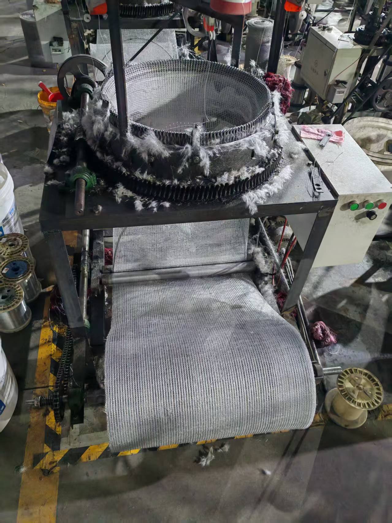
Knitted wire forms interconnected loops rather than regular warp-and-weft square apertures. Folding, corrugating, layering, rolling or compression creates a three-dimensional network of flow paths.
Performance depends on wire diameter, loop structure, layers, thickness, compression, velocity and contaminants. Mesh count cannot directly define filtration rating. Solid-particle filtration requires efficiency at specified sizes; droplet capture also involves collision, coalescence and drainage.
2. Four Common Constructions
| Form | Specification focus |
|---|---|
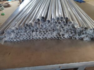
| Roll | Width, length, wire diameter and loop structure for further processing. |
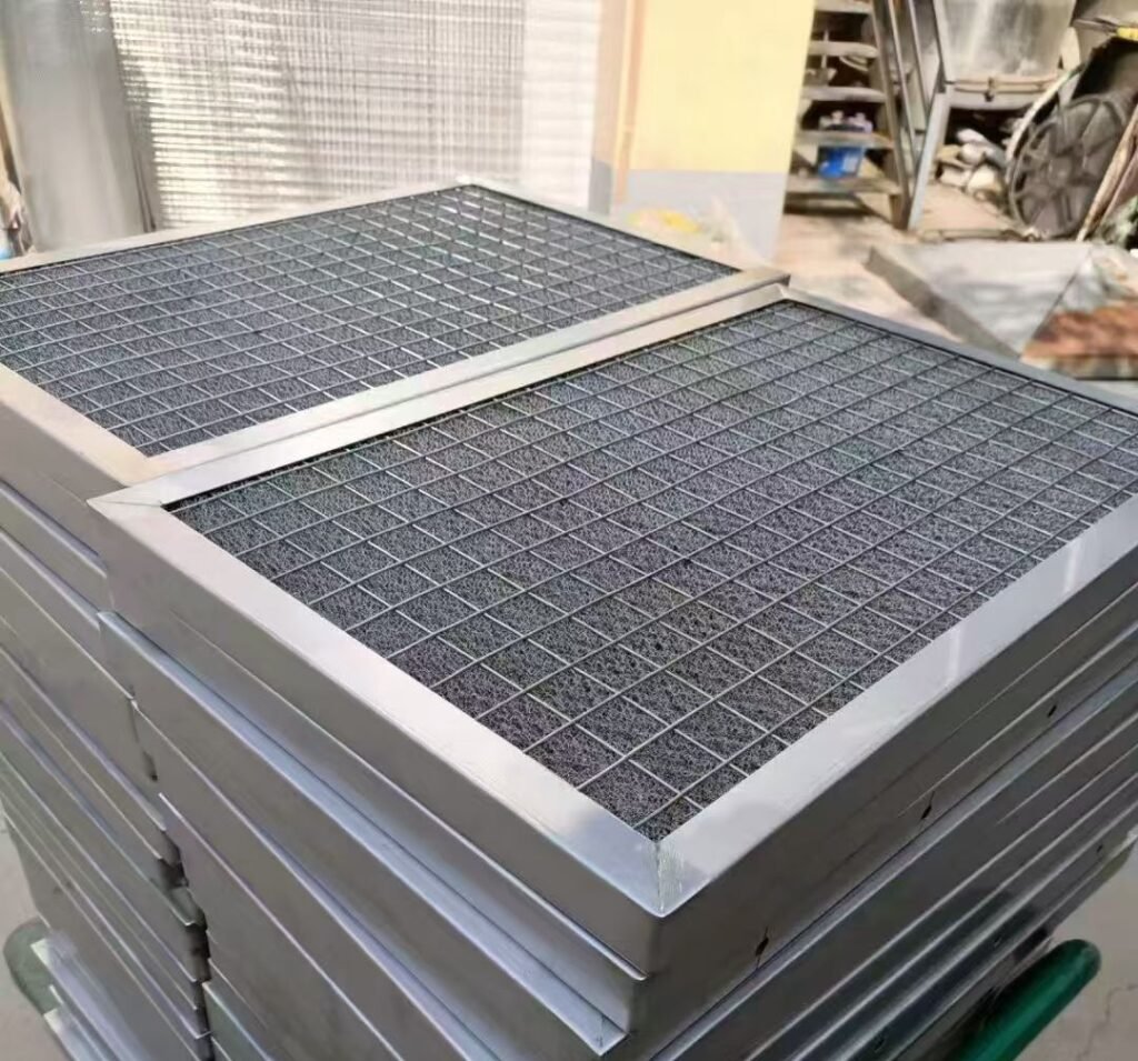
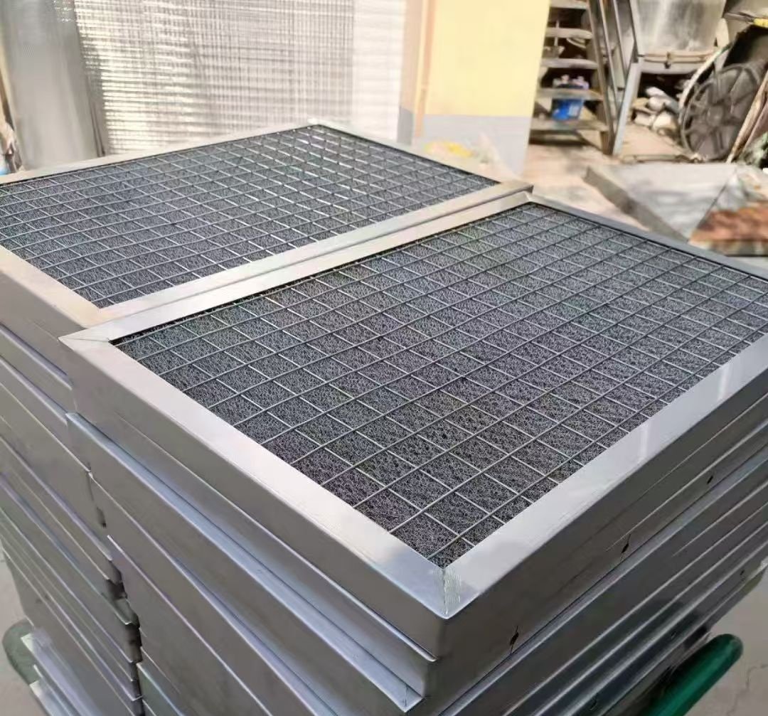
| Framed panel | Thickness, projected effective area, support grids, frame and sealing. |
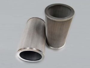
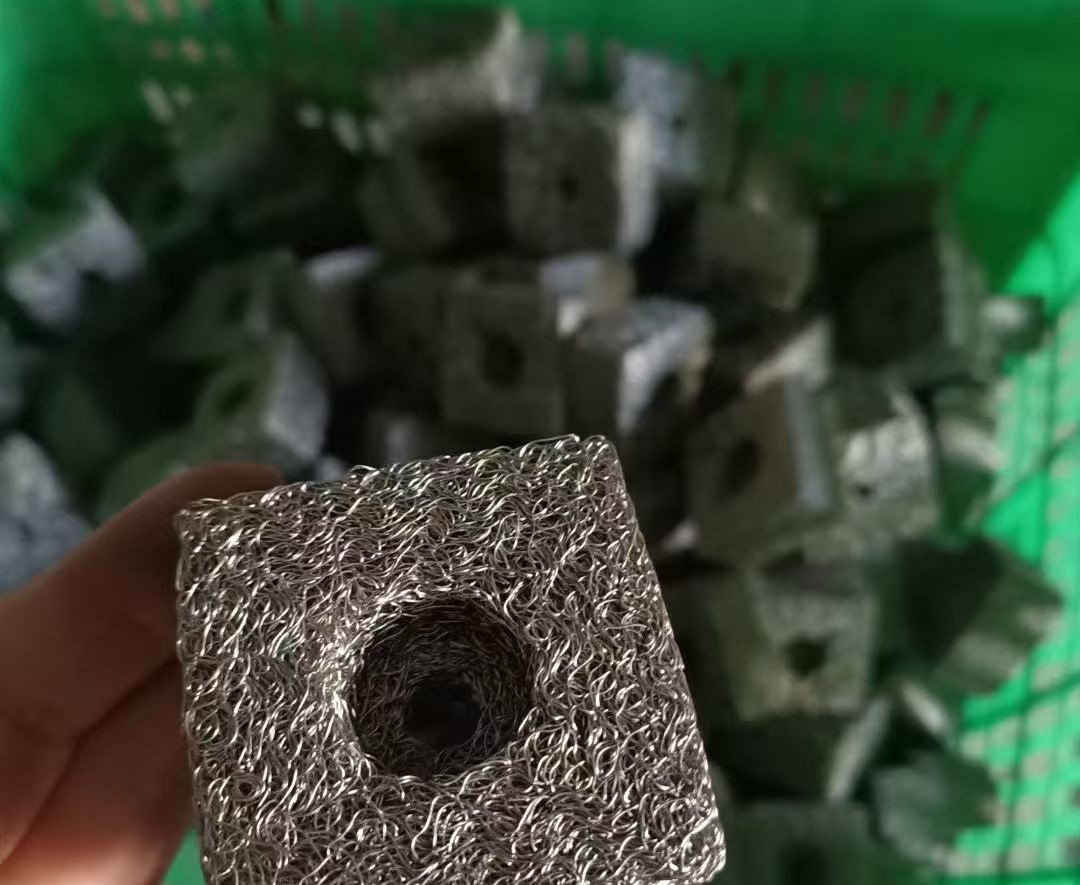
| Compressed component | Wire structure, unit weight, bulk density, thickness and tolerances. |
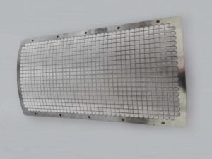
| Custom shape | Housing geometry and fit, often using a compressed-mesh route. |
These are purchasing categories, not four independent mechanisms or performance grades. A roll leaves processing flexible; a frame retains area and thickness; a compressed part fixes a three-dimensional shape.
3. Contaminants and Operating Fluid
Solid particles
Provide particle-size distribution, concentration, shape, hardness or stickiness, and allowed downstream contamination. Do not assume a knitted structure meets fine-particle retention targets. Confirm by testing and use a separate fine-filter stage if needed.
Droplets and mist
Specify droplet distribution, gas velocity, liquid properties and drainage. Poor drainage or excessive velocity can cause accumulation and re-entrainment. Clean dry pressure drop does not describe wet operation, and demister results cannot be transferred to solid-particle filtration.
Gas or liquid
Identify the medium, flow, temperature and pressure. For standard/normal gas volume, state reference temperature, absolute pressure and dry/wet basis. Use actual inlet volume for face velocity rather than mixing flow bases.
For mist removal, see wire mesh demister pad selection.
4. Filtration and Pressure Drop
Increasing wire mass, thickness or compression changes contaminant interaction and flow resistance. Seek an acceptable balance rather than maximum density.
Set allowable pressure drop early. Separate initial clean-filter loss from the rise during loading. Fans, pumps and compressors need a workable pressure budget through the maintenance interval; initial pressure drop alone is incomplete.
5. Wire Diameter and Structure
The same wire diameter does not guarantee the same media. Loop geometry, corrugation, layer count, orientation and compression can change the internal network.
Evaluate wire diameter with structure, layer arrangement and compression. ‘Finer wire means finer filtration’ and ‘coarser wire means lower loss’ are unreliable stand-alone rules.
6. Density, Porosity and Compression
ρb = m/V describes bulk density. Use wire mass excluding frames, grids and other parts. Include internal voids in the mesh envelope volume, but exclude central through-holes and other macroscopic cavities. With g and cm³, density is g/cm³. State free or installed condition.
For a single-metal component without coating or fillers, ε = 1 − m/(ρs × V) estimates average total void fraction. Use compatible units; ε is dimensionless and becomes a percentage when multiplied by 100%.
Density is not filtration rating; porosity is not pore size; pore size is not measured efficiency. Average porosity does not establish local uniformity, pore connectivity or a micron cutoff. Installation compression changes the structure again.
The density and porosity calculator requires a suitable geometry and calculation basis.
7. Thickness, Area and Flow Direction
Specify media thickness in the flow direction. Greater thickness can alter capture and loss, but is not automatically better.
Frames and supports reduce the available area. For superficial face velocity, v=Q/A, A is the projected effective area normal to flow, not the sum of all wire surfaces. Use compatible units and the same area/flow basis in comparisons.
8. Material, Loading and Cleaning
Select material from the medium, temperature, corrosion and cleaning chemistry. 304 and 316L stainless steel are common candidates; exact nickel-based alloys, Monel or other metals may suit specific conditions.
Define dirt-holding capacity with contaminants, loading method and terminal pressure drop or performance endpoint. Reusability depends on removal of deposits without damage and recovery of pressure drop and filtration behavior.
After cleaning, check corrosion, broken wires, dimensions, seals and performance. Replace damaged media or parts with unremovable deposits according to agreed criteria. A clean appearance does not prove recovery.
9. Installation and Bypass
Fluid that passes around the media defeats the intended filtering action. Provide housing dimensions, fit tolerances, seals, flow direction and axial/radial compression.
Distinguish as-supplied from as-installed geometry. Additional compression changes density, contacts and flow paths; correct free-state dimensions do not guarantee the intended installed state.
10. Specification Checklist
- Medium, contaminants, size distribution, concentration and actual flow.
- Pressure-drop budget, temperature, pressure and corrosion conditions.
- Shape, dimensions, material, wire diameter, thickness and weight/density if known.
- Frame, supports, projected effective area and seals for panels.
- Critical tolerances and installation compression for compressed parts.
- Drawing, sample and mating housing for custom replacements.
- Cleaning method, maintenance interval and replacement criteria.
Do not invent unknown values. Real operating conditions are more useful than an unsupported micron rating or target density.
11. Prototype and Validation
For new projects, follow conditions → initial design → prototype → pressure-drop and filtration tests → adjustment → production. Established replacements can follow documented original requirements.
Record medium, temperature, flow reference, effective area, size distribution, concentration, efficiency method and terminal pressure drop. For solids, specify efficiency at target sizes and count or mass basis. For droplets, separately define liquid properties, drainage and re-entrainment limits.
Agree acceptance and test responsibility; customer or third-party validation may be used. Used samples can be contaminated, worn or permanently compressed. Reverse engineering supports manufacturing requirements but cannot replace performance testing.
12. Frequently Asked Questions
What micron rating is possible?
No single value applies to every knitted mesh filter. Specify efficiency at particle size with the fluid, flow and pressure drop. An undefined micron number is not an absolute-retention promise.
Does greater density improve filtration?
Not necessarily. Determine density with wire, structure, thickness, flow and allowable loss.
How do framed and compressed filters differ?
A frame supports an area of media; compression establishes a shaped three-dimensional part. Both need defined media and installed conditions.
Can it be cleaned?
Only if deposits can be removed without damage and performance recovers. Check structure and sealing as well as pressure drop.
Can you reproduce an old sample?
A sample supports analysis and prototyping. Send the housing and conditions to identify changes caused by service.
13. Conclusion and Related Resources
Define a knitted wire mesh filter by its working duty. Wire diameter, loop structure, weight/density, thickness, material and installed fit must work together within the efficiency and pressure-drop targets.
Explore mesh rolls, panel filters and compressed components. The dry pressure-drop study of knitted-wire demisters addresses dry demister media, not universal wet-operation or particle-retention performance.
Discuss Your Knitted Mesh Filter Requirements
- Application-based customization: provide operating conditions, installation space and functional targets to establish an initial specification and prototype.
- Drawing-based customization: provide materials, dimensions, tolerances, connections and agreed acceptance requirements.
- Sample-based customization: provide the existing part and mating components; evaluate wear, contamination and permanent deformation before confirming a replacement.