By Jack Sun · Updated October 22, 2026
Alkaline, PEM and AEM electrolysis all use electricity to split water into hydrogen and oxygen. Their main differences are the electrolyte, the structure separating the reaction compartments, and the ions carrying charge between the electrodes. These differences affect electrode environments, materials, component structures and operating conditions. [1]
For porous metals, the technology provides a starting point for understanding the application. Titanium felt is one material option for the anode porous transport layer in PEM electrolysis. Nickel felt can provide transport, conductive support or a catalyst substrate in particular alkaline and AEM electrode designs. Its exact role depends on where it sits in the electrolyzer.
A quick comparison of alkaline, PEM and AEM electrolysis
Here, ALK means conventional liquid alkaline water electrolysis, also called AWE or AEL. PEM means proton exchange membrane electrolysis, and AEM means anion exchange membrane electrolysis.
| Comparison | ALK: liquid alkaline | PEM | AEM |
|---|---|---|---|
| Electrolyte and separating structure | Aqueous alkaline electrolyte and porous diaphragm | Proton exchange polymer membrane | Anion exchange polymer membrane |
| Main charge-carrying ion | OH− | H+ | OH− |
| Electrode environment | Alkaline | Acidic membrane/ionomer environment and oxidizing anode conditions | Alkaline; specific conditions depend on the feed and membrane system |
| Reaction products | Hydrogen at the cathode; oxygen at the anode | Hydrogen at the cathode; oxygen at the anode | Hydrogen at the cathode; oxygen at the anode |
These are differences between technology families. Feed arrangements, pressure, materials and component geometry remain design-specific. [1][2] Establishing these basics makes efficiency, cost and material comparisons easier to interpret.
How ALK, PEM and AEM work
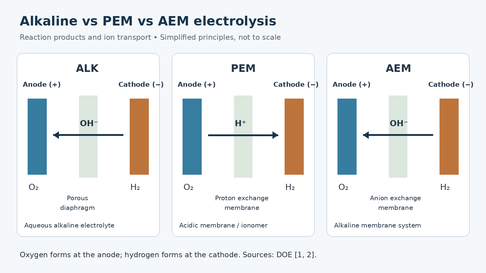
ALK: ions travel through an alkaline electrolyte
Conventional alkaline electrolysis uses an aqueous alkaline electrolyte between the electrodes, commonly potassium hydroxide or sodium hydroxide. A porous diaphragm separates the reaction compartments while allowing ionic transport through the electrolyte.
At the cathode, water participates in the reaction that produces hydrogen and hydroxide ions. OH− moves toward the anode, where the oxygen-producing reaction takes place. The diaphragm, electrolyte and electrodes together establish the reaction and conduction paths. [1]
This creates distinct material tasks. The electrode and its supporting structure need electronic conductivity and compatibility with the alkaline environment. The diaphragm separates the gases while allowing ionic transport. Keeping those functions separate helps identify whether a reference to “porous nickel” concerns an electrode component or a separating structure.
PEM: the membrane conducts protons
PEM electrolysis uses a proton exchange membrane. Water reacts at the anode to form oxygen, protons and electrons. Protons move toward the cathode through the membrane and associated ionomer paths; electrons travel through the external circuit to participate in hydrogen production at the cathode. [1]
The membrane allows the electrodes to form a compact assembly around it. The acidic and oxidizing conditions at the anode place demands on the stability of catalysts, transport layers and adjacent metal surfaces.
Both environmental stability and electrical contact matter. A conductive metal does not automatically provide sufficiently low resistance at every interface after assembly.
AEM: an anion exchange membrane in an alkaline reaction system
AEM and ALK both use OH− as the main charge-carrying ion. AEM introduces an anion-conducting polymer membrane into the electrode assembly, so its structure and interfaces also involve the interaction between membrane, ionomer and catalyst layers.
This route creates opportunities for non-precious-metal catalysts and lower-cost metal components. Feed arrangements vary: pure-water operation and operation with a supporting electrolyte need separate evaluation. Membrane and ionomer conductivity, stability and electrode interfaces remain important design and research issues. [2]
Sharing an alkaline reaction environment therefore explains only part of the relationship. Conventional ALK and AEM still differ in their separating structures, electrode assemblies and feed designs.
What the differences mean in operation
Changing power and start-stop operation
PEM is often discussed in connection with rapid load response and compact construction. Liquid alkaline systems can also accommodate changing power input through equipment and control design.
For example, thyssenkrupp nucera describes dynamic operation in its public alkaline water electrolysis information. [3] The label “ALK” alone therefore cannot establish whether a particular system suits a variable power source. Equally, one manufacturer’s capabilities do not describe every alkaline system.
Useful comparisons ask about the operating load range, cold-start time versus warm load adjustment, gas crossover at low load, and degradation during cycling. Together, these determine how the power source and electrolyzer work together.
Cost includes more than the material price
The three routes use different electrode, membrane, catalyst and metal-component systems. Precious-metal catalysts and associated components are important in PEM cost discussions. AEM offers the potential to reduce some costs through non-precious materials. [2][4]
A cheaper substrate does not necessarily produce cheaper hydrogen. Electricity consumption, equipment utilization, maintenance, component replacement and gas treatment can all affect operating cost. Material prices help explain technology differences, but cannot establish a universal cost ranking for complete systems.
Pressure, water supply and gas treatment
Hydrogen leaving a stack still needs to meet the pressure, moisture and impurity requirements of its intended use. A purity figure needs a measurement location and an explanation of any gas treatment. Pressure comparisons should distinguish operating pressure from the pressure difference between the two sides.
Water treatment, electrolyte management, gas-liquid separation and other auxiliary equipment must work with the stack. [2] A transport layer or material data sheet answers only part of that system question.
Comparing efficiency, energy consumption and lifetime
Efficiency figures need the same measurement boundary
Electrolysis efficiency can refer to a single cell, a stack or a complete system. A system-level assessment also includes relevant auxiliary energy consumption. Measurement and calculation boundaries need to be aligned before comparing published figures. [5]
For electricity consumption in kWh per kilogram of hydrogen, check where electricity is metered, how hydrogen output is measured, and whether gas treatment falls inside the boundary.
HHV and LHV can give different percentages for the same consumption
The higher heating value (HHV) and lower heating value (LHV) treat the heat associated with water formed during hydrogen combustion differently. The JRC gives hydrogen heating values of approximately 39.4 kWh/kg on an HHV basis and 33.3 kWh/kg on an LHV basis. [5]
Consider an illustrative system consuming 55 kWh of electricity per kilogram of hydrogen within a defined boundary:
- LHV efficiency: 33.3 ÷ 55 ≈ 60.5%.
- HHV efficiency: 39.4 ÷ 55 ≈ 71.6%.
This is a calculation example using the heating values above, not a measured result for our equipment or materials. Neither the system nor its electricity consumption has changed. The percentage changes because the heating-value basis changes.
Lifetime needs operating conditions and an end criterion
A lifetime in hours needs a degradation threshold, load profile, cycling conditions and other test conditions. The duration of one experiment also provides a different kind of evidence from a complete lifetime assessment.
DOE’s PEM technical targets distinguish performance, degradation rate, lifetime and cost, and require relevant targets to be met together in the same stack or system. [4] Such tables also distinguish reported status from future targets. Neither should automatically be treated as a commercial product guarantee.
The same reasoning applies to materials. Changing a transport layer may affect a particular cell result, while long-term operation still depends on the combined components and conditions.
What porous metal components do
In some electrolyzer designs, porous metal components sit between a catalyst layer and adjacent parts such as a flow field. They contribute to fluid transport, electrical contact and mechanical support. Names vary between designs, so location and function provide a clearer guide than the component name alone. [6][7]
| Component or function | Main task | What to distinguish |
|---|---|---|
| Diaphragm or ion exchange membrane | Separates reaction compartments and supports the relevant ionic transport | Electronic conduction through a metal skeleton is a different function |
| Catalyst layer | Provides active sites for electrochemical reactions | The substrate and deposited catalyst material have separate roles |
| Porous transport layer (PTL) | Supports fluid transport, electrical contact and mechanical support | Its role depends on the electrode side and assembly design |
| Flow field and current-collection components | Distribute fluids and collect or transfer current | Functions may be separate from, or integrated with, a transport-layer design |
Pores and metal fibers provide different transport paths
Fluids move through the pore network; electrons travel mainly through the connected metal skeleton. In PEM electrolysis, protons travel mainly through the membrane and associated ionomer paths. [1]
Liquid passing through a felt does not mean that the felt performs the membrane’s ion-conduction function. These separate paths explain why thickness, pore structure and surface condition require different kinds of attention.
Porosity, contact and support work together
Increasing pore space changes fluid pathways as well as the metal skeleton and its contact relationships. Assembly compression also affects contact with neighboring components.
Research on PEM anode PTLs, for example, evaluates contact resistance between the transport layer and the catalyst layer. [6] Bulk conductivity, interface contact and fluid transport are related properties, but one cannot stand in for another.
For a particular felt, the useful question is whether it can meet the required transport, contact and support functions together under the specified assembly conditions.
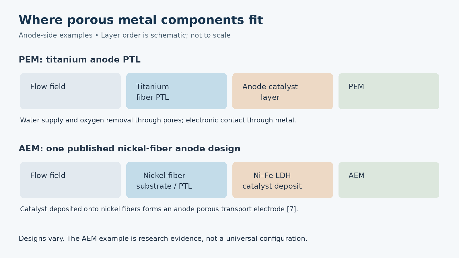
Where titanium and nickel felt fit
Titanium felt as a PEM anode porous transport layer
In a typical PEM anode assembly, a titanium-based PTL sits between the anode catalyst layer and the flow field. Connected titanium fibers provide a metal network, while the pores help supply water to the reaction region and remove oxygen. The structure also provides electrical contact and mechanical support. [6]
Titanium’s surface condition matters here. An oxide layer that protects the metal can also increase contact resistance with adjacent components. Environmental stability and sustained electrical contact therefore need separate evaluation.
The difference between coated and uncoated titanium felt is mainly at the surface and interfaces. A particular coating or surface treatment can be designed around contact and stability, but its effect depends on the material, process and operating conditions. Research comparing PTL treatments reports differences between them. [8]
A coating does not replace the need for suitable dimensions, pore structure and assembly fit. A conductive or protective coating also has a different purpose from a catalyst layer.
We supply coated and uncoated titanium sintered felt and discuss products against drawings and agreed surface requirements. Material delivery requirements and performance after installation in an electrolyzer belong to manufacturing acceptance and application validation respectively.
For more on position, parameters and assembly, see titanium felt as a PTL in PEM electrolyzers.
Nickel felt in alkaline and AEM electrode structures
Nickel-based materials are closely associated with alkaline electrode systems. A nickel-fiber skeleton can provide conduction, support and transport paths in a particular design, and can serve as a substrate for a deposited catalyst.
In one AEM study, researchers deposited a nickel-iron layered double hydroxide catalyst on a nickel-fiber substrate and used it as an anode component, with a different transport-layer material on the cathode. [7]
This illustrates both the substrate and transport-related roles of nickel fibers, and the need to identify anode and cathode configurations separately. The paper’s catalyst, preparation process and performance results apply to its research specimens.
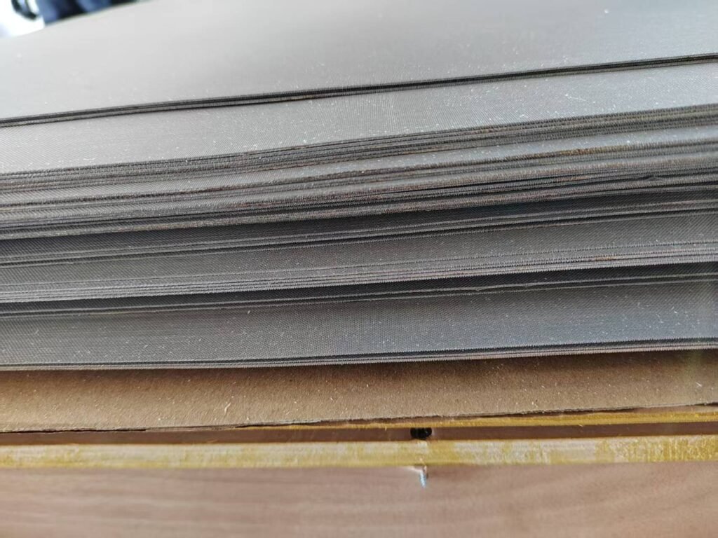
Nickel-based electrodes and porous supports also have applications in conventional alkaline electrolysis, although equipment designs use different electrode forms. In AEM, nickel felt’s position also depends on where the catalyst is deposited, the membrane-electrode assembly and adjacent transport components.
When describing nickel felt for an electrolyzer, clarify the electrode side, whether the supplied part is a bare substrate, surface-treated material or catalyst-loaded electrode, and how neighboring components contact it. These details turn a material name into a defined component task.
Connecting the material role to a drawing
The technology helps identify the environment and material direction. The electrode position identifies the reaction side and neighboring components. A drawing and delivery requirements then define shape, thickness, surface condition and assembly relationships.
A drawing, existing specification or sample photograph is a useful starting point for a discussion. Any remaining manufacturing and inspection details can then be clarified individually.
For a fuller material comparison, see titanium felt versus nickel felt. For structure and contact issues, continue with how titanium felt quality affects PEM electrolyzers.
Frequently asked questions
Why are ALK and AEM different if both conduct OH−?
They share an alkaline reaction background but use different separating and ion-conducting structures. Conventional ALK uses a liquid alkaline electrolyte and porous diaphragm. AEM uses an anion exchange membrane, making the membrane, ionomer and catalyst-layer interfaces important parts of the design. [1][2]
Does AEM always avoid precious-metal catalysts?
AEM provides an opportunity to use non-precious-metal catalysts. The actual electrode materials remain design-specific. The technology name does not prescribe every catalyst, and research and commercial configurations need to be checked separately. [2]
Can nickel felt directly replace titanium felt at a PEM anode?
Shape and conductivity alone cannot justify that replacement. The PEM anode environment, surface stability and contact requirements all belong in the assessment. A substitution needs validation for the particular design; experience in an alkaline system cannot establish suitability at a PEM anode.
Can filtration-grade sintered felt serve directly as an electrolyzer PTL?
First compare the required functions. Particle-retention criteria for a filter differ from an electrolyzer’s transport, electrical-contact, surface and assembly requirements. A shared sintered-fiber structure describes only part of the material. Suitability needs evaluation against the component requirements.
How does SOEC differ from these three technologies?
Solid oxide electrolysis typically uses an oxygen-ion-conducting ceramic at elevated temperature and can incorporate thermal energy input. Its materials and energy boundary differ from the three low-temperature routes discussed here. [1] Electricity comparisons should explain how heat input is accounted for.
From electrolysis technology to a defined component
Start with the electrolyte and separating structure, then consider the resulting environment, operating requirements and component roles.
That makes the role of titanium or nickel felt clearer: the material must suit the environment, the fiber skeleton provides conduction and support, pores carry fluids, and the surface interacts with adjacent parts to establish contact. Connecting these functions to a specific position explains why a felt is used and what it still needs to satisfy.
Further reading and technical sources
Related articles and products
- Titanium sintered felt: properties, applications and coatings
- Titanium felt as a PTL in PEM electrolysis
- Titanium felt and nickel felt compared
- Nickel fiber sintered felt
- Sintered metal fiber felt family
Technical sources
- U.S. Department of Energy. Hydrogen Production: Electrolysis. Basic operating principles, ion transport and SOEC scope.
- U.S. Department of Energy. Hydrogen Shot: Water Electrolysis Technology Assessment, 2024. Technology structures, materials, auxiliary systems and AEM research issues. This historical assessment is not a statement of the 2026 commercial market.
- thyssenkrupp nucera. Industrial-Scale Alkaline Water Electrolysis. Manufacturer-specific example of dynamic alkaline operation.
- U.S. Department of Energy. Technical Targets for Proton Exchange Membrane Electrolysis. Joint assessment of performance, degradation, lifetime and cost.
- European Commission, Joint Research Centre. Energy efficiency of water electrolysers for hydrogen production, JRC140567. Efficiency boundaries and hydrogen HHV/LHV. The 55 kWh/kg input in this article is an illustrative assumption.
- On the contact resistance between the anode and the porous transport layer in a proton exchange membrane water electrolyzer, 2024. Anode/PTL contact resistance.
- Galkina et al. Stability of Ni–Fe-Layered Double Hydroxide Under Long-Term Operation in AEM Water Electrolysis, Small, 2024. A specific nickel-fiber anode research configuration; catalyst preparation and test results are not claimed as our manufacturing capabilities.
- Degradation of PGM and PGM-free Coatings on PEMWE Porous Transport Layers, ACS Applied Materials & Interfaces, 2025. Treatment-dependent contact and durability behavior.
About the author: Jack Sun has long worked in metal wire mesh weaving and industrial filter element manufacturing. Filtalloy is based in Anping, Hengshui, Hebei, China, known as the wire mesh capital.