Quick answer: Whether sintered fiber felt needs support mesh depends on how the medium is supported in the finished filter and what it experiences during filtration, cleaning and fabrication. The mesh position, connection and intended function provide the basis for that decision. “Mesh supported” alone does not define the construction.
If you already have a filter drawing, you may be wondering why a mesh layer is needed next to the felt when there is a perforated core inside. For a replacement made from an existing sample, the questions may be different: can that mesh be omitted, or can another mesh with the same count be used?
Those questions become clearer when you look at the actual assembly. This guide connects support types with flow direction, specifications, fabrication and inspection, so the support requirements can be carried through to the drawing and delivery checks.
1. Common types of support
Sintered metal fiber felt is a porous network of metal fibers bonded at their contact points. Woven support mesh consists of interlaced wires. The two can form a bonded composite, or separate layers can be fitted during assembly.
The following components have different positions and functions:
| Component | Construction and function | Drawing information |
|---|---|---|
| Mesh sinter-bonded to the felt | Part of the composite medium, rather than a layer simply placed against it | One or both faces, mesh specification, bonding method and total composite thickness |
| Separately fitted mesh | Support, spacing or drainage, as defined by the assembly | Position, retention, contact and clearance |
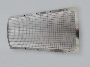
| Perforated core or similar internal structure | Support for the cartridge, including the relationship between its openings and the medium | Opening shape and size, contact points and end connections |
| Outer cage, protective mesh or reinforcement bands | Protection, restraint or support of specified regions | Coverage, fixing points and position relative to the medium |
A useful point to clarify is that two quotations marked mesh supported may describe different layer arrangements. A cross-section showing where the mesh sits, what it connects to and what it does is more informative than the term alone.
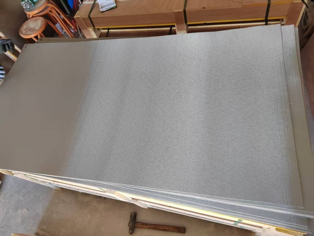
Our sintered metal fiber felt product page describes media without mesh, with single-sided mesh and with double-sided mesh. It also explains the usual composite route: sintering the felt first, then bonding the mesh and felt in a second sintering step. The actual construction remains part of the order specification.
2. The roles of the perforated core and adjacent mesh
A perforated core and adjacent mesh can provide support at different scales. Their roles become clearer from the surfaces that actually contact the felt.
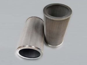
Differential pressure applies a load across the medium. A perforated tube can support the cartridge while the felt above each opening still spans a region without direct contact with the tube. How that region behaves depends on the opening size, medium, adjacent mesh and applied differential pressure.
When reviewing a drawing with an internal core, useful questions include:
- Does the medium contact the supporting surface, or is there a gap?
- What provides local support over the core openings?
- How does the load pass through the mesh and core to the fixing points and ends?
Adjacent mesh may contribute local support. An outer cage or band may protect or constrain particular areas. Their contact and fixing arrangements explain their actual roles; calling every visible metal component “support” can hide an important gap in the construction.
If you have a cross-section, you can follow the assembly from the felt through the core to the end connections. If no drawing is available, the visible layers and joints on a sample provide a starting point. Hidden or inaccessible regions can be recorded as items for confirmation.
3. Flow direction and support position
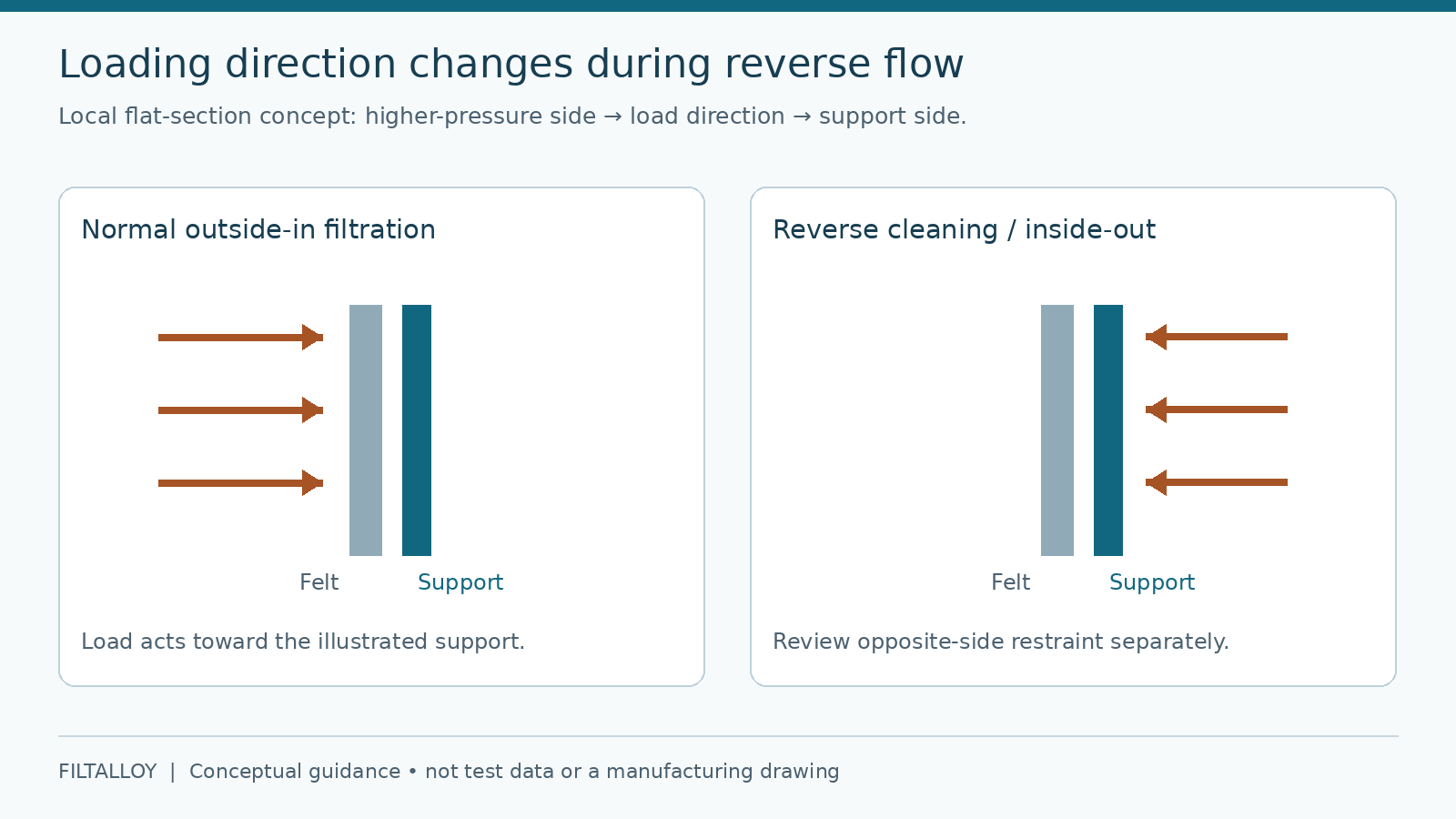
A support arrangement that works in normal filtration can experience a different loading relationship during reverse cleaning.
Consider a cylindrical filter operating with outside-to-inside flow. Normal differential pressure loads the medium inward, where an internal supporting surface may carry part of that load. If cleaning reverses the flow, the medium may be loaded outward and move away from the original supporting face. The outer restraint, layer bonding and connections then become relevant.
This example explains the change in load direction. It does not predict that every such filter will deform or that double-sided mesh is always necessary. It shows why normal flow alone is an incomplete description of service.
A useful construction drawing includes:
- Normal flow direction and the high-pressure side.
- The relative positions of the felt, mesh and core.
- Backwashing or cleaning direction, and any known reverse conditions during shutdown or switching.
- The components carrying the load in each direction.
System pressure and filtration differential pressure also describe different conditions. System pressure is the pressure level within the equipment; differential pressure is the difference between defined measurement points. Pump discharge pressure alone does not identify the load across the felt.
When a supplier provides a pressure rating, you can check whether the tested object was a flat specimen, composite medium or complete cartridge, along with the temperature, loading direction, support conditions and acceptance criteria. Those details establish whether the result is relevant to your assembly.
4. Support mesh specifications and fit
In a custom project, the operating conditions or original equipment requirements may already define the filtration medium. The next task is fitting the support to that medium, the available space and the service conditions.
“Stainless steel, a specified mesh count” is only part of the description. The same count can use different wire diameters, changing the openings, thickness and contact geometry. Alloy grade, weave, aperture or count, wire diameter, thickness and position relative to the felt are also relevant.
| Question | Conditions to review together | Design or fabrication consequence |
|---|---|---|
| How is local support provided? | Openings, wire diameter, contact distribution and load direction | Support spans and the load path |
| Are usable flow passages maintained? | Mesh layers, pleat spacing, clearances and the complete flow path | Pressure loss and passage layout |
| Can the assembly be formed and fitted? | Total layer thickness, pleat geometry, rolling and installation space | Forming requirements and dimensional fit |
| How does the assembly behave during cleaning? | Cleaning direction, method, materials and retention | Inspection points and validation conditions |
For pleated filters, unfolded area is only one input. Equal media areas within the same outside diameter can still have different pleat spacing, layer thickness and flow passages. Adding mesh also changes the composite thickness used in the forming and assembly review. The filter area calculator can help check geometry; performance needs evidence from the relevant finished construction.
These checks are useful even if you are not carrying out a structural calculation yourself. They help identify missing drawing or quotation details and show which questions need a sample or finished-filter test.
5. Layer connections and fabrication requirements
The connection method determines what needs checking. Two layers touching in a photograph do not establish how they are joined.
When mesh is sinter-bonded to the felt, it forms part of the composite medium. Drawings and purchase requirements can define the layer sequence, total thickness and subsequent forming requirements. If bonding is an acceptance requirement, an appropriate inspection method and acceptance criteria need agreement before production.
For separately fitted mesh, the relevant details include positioning, edge retention, possible movement and whether contact areas need protection against abrasion.
Cutting, pleating and rolling also change the material geometry. Pleat roots, tips, seams and layer positions need review in the formed assembly. An undamaged flat sheet answers only part of the quality question.
The material list needs the same level of detail. A 316L felt designation does not identify the grades of the mesh, core or joining materials. Those components can also contact cleaning fluids, so operating and cleaning conditions belong in the same material review. Our metal filter troubleshooting guide provides a related framework for recording condition and operating changes.
Support contact and end fixing belong to one load path
A cross-section can follow the loaded region from the felt through adjacent mesh and the core to the ends. If a core or cage ends short of a connection, the drawing should identify what carries the load across that region. A visible tube inside the cartridge does not establish that every seam, pleat end or attachment is supported.
Review separately how the medium is joined to the ends and how the complete element seals into its housing. A restraint can carry mechanical load without being the fluid seal. Conversely, a seal that prevents bypass does not establish the strength of the pleated assembly. These functions may share components, but need their own requirements.
Changing a support termination, end joint or sealing position can therefore require both construction and interface review. Preserve the drawing revision and normal/reverse directions. The pleated cartridge page shows supply configurations, and the pleated-filter validation plan connects each changed feature to the checks it affects.
6. Sample approval and finished-filter inspection
Defining what the sample is meant to demonstrate makes it easier to carry its approval into the delivery requirements.
| Stage | Main checks | Use of the result |
|---|---|---|
| Media specimen | Layers, positions, thickness, edges and surfaces | Confirm that the material construction matches its description |
| Forming and assembly | Pleats, rolled regions, layer alignment, support contact and retention | Check the fabricated construction and fit |
| Complete cartridge | Agreed dimensions, connections, structural and performance checks | Judge acceptance under recorded test conditions |
| After cleaning | Deformation, damage, connections, pressure-loss recovery and any required retention checks | Support the decision on return to service |
One point deserves attention: lower pressure loss after cleaning shows a change in flow resistance, but it does not by itself demonstrate restored particle retention. Return-to-service decisions need the agreed integrity and performance checks.
Before production, the inspection object, methods, conditions, sampling and acceptance criteria can be included in the requirements. Pressure or reverse-load checks also need a defined direction. Delivery can then be assessed against agreed results rather than different interpretations of “strong enough.”
7. Information for a custom filter project
You can begin the discussion before every detail is available. Separating known information from unknowns and details recoverable from a sample helps identify the next step.
Operating conditions. Include the fluid and contaminants, retention target, flow, temperature and viscosity where relevant. Record system pressure separately from operating, abnormal and reverse-cleaning differential pressure, with measurement locations.
Construction information. Drawings, cross-sections, envelope and connection dimensions, critical tolerances, installation space and both flow directions help describe the assembly. A sample can show visible layers and joints; inaccessible details can be marked for confirmation.
Delivery requirements. Identify component materials, layer connections, cleaning methods and the separate checks required for samples and finished filters.
For a replacement, dimensions and visible construction are often the starting point. The original rating, alloy and permissible differential pressure may need other records. Keeping those unknowns explicit is more useful than filling them with estimates based on appearance.
Frequently asked questions
Does support mesh improve filtration accuracy?
Support and retention are separate functions. If an additional layer also filters, the complete construction needs an agreed retention assessment. Adding support mesh alone does not establish improved accuracy, and its mesh count is not the felt’s micron rating.
Does thinner felt always need double-sided mesh?
Thickness is one condition among several. Medium structure, geometry, support spans, normal and reverse loads, and connections all matter. Those conditions provide the basis for determining the support arrangement.
Can the original support mesh be omitted in a replacement filter?
That is a design change. It calls for a review of the original layer’s role, local support, flow direction, cleaning and forming requirements. The original construction is a useful reference, but appearance or satisfactory normal operation alone cannot establish that a revised arrangement is suitable.
Can another mesh with the same count be used?
Alloy, weave, wire diameter, thickness, openings and retention also need comparison. Matching the count establishes only part of the specification, rather than equivalent support, flow and assembly behavior.
Can media tensile strength be converted into an allowable cartridge differential pressure?
Not directly. Tensile data apply to a defined specimen and loading method. Cartridge differential-pressure capability also depends on geometry, local spans, core, seams and end fixing. Confirmation needs to address the actual assembly and loading direction.
Conclusion
Support design connects the medium, adjacent mesh and finished-cartridge structure. Flow direction defines the loading direction; mesh and fixing arrangements determine the support relationship; forming and assembly establish the final geometry. Drawings, samples and acceptance requirements need to describe that same design.
For an existing filter, a cross-section identifying the felt, mesh, core and both flow directions provides a practical starting point. Together with operating conditions, it helps establish what is already defined and what still needs validation. You can share your drawing and operating conditions with Filtalloy to discuss the construction and checks.
Technical references
- Kansai Wire Netting filter catalogue: examples of mesh-reinforced fiber media. The catalogue’s specifications do not define Filtalloy’s order specifications.
- Porvair Sinterflo F: background on pleatable metal-fiber media.