
By Jack Sun · Updated October 23, 2026
Quick definition
Filter troubleshooting means recording pressure drop, flow, fluid condition, downstream particles and the visible condition of an element together, then checking measurement, operation, installation and structure. One symptom can have several explanations. High pressure drop does not automatically mean clogging; low pressure drop does not prove that filtration is working.
A filter may show high differential pressure during a cold start and return to its usual range after the fluid warms. On another occasion, differential pressure may fall suddenly while downstream particle counts increase. These events require different checks. Recording when the change occurred, the flow and the fluid condition is more useful than immediately replacing the element with a coarser grade.
This guide covers general checks for woven wire mesh, sintered mesh, metal fiber felt and sintered powder elements. Alarm settings, terminal differential pressure and cleaning parameters must come from the equipment and element documents for the application.
1. Establish a comparable baseline
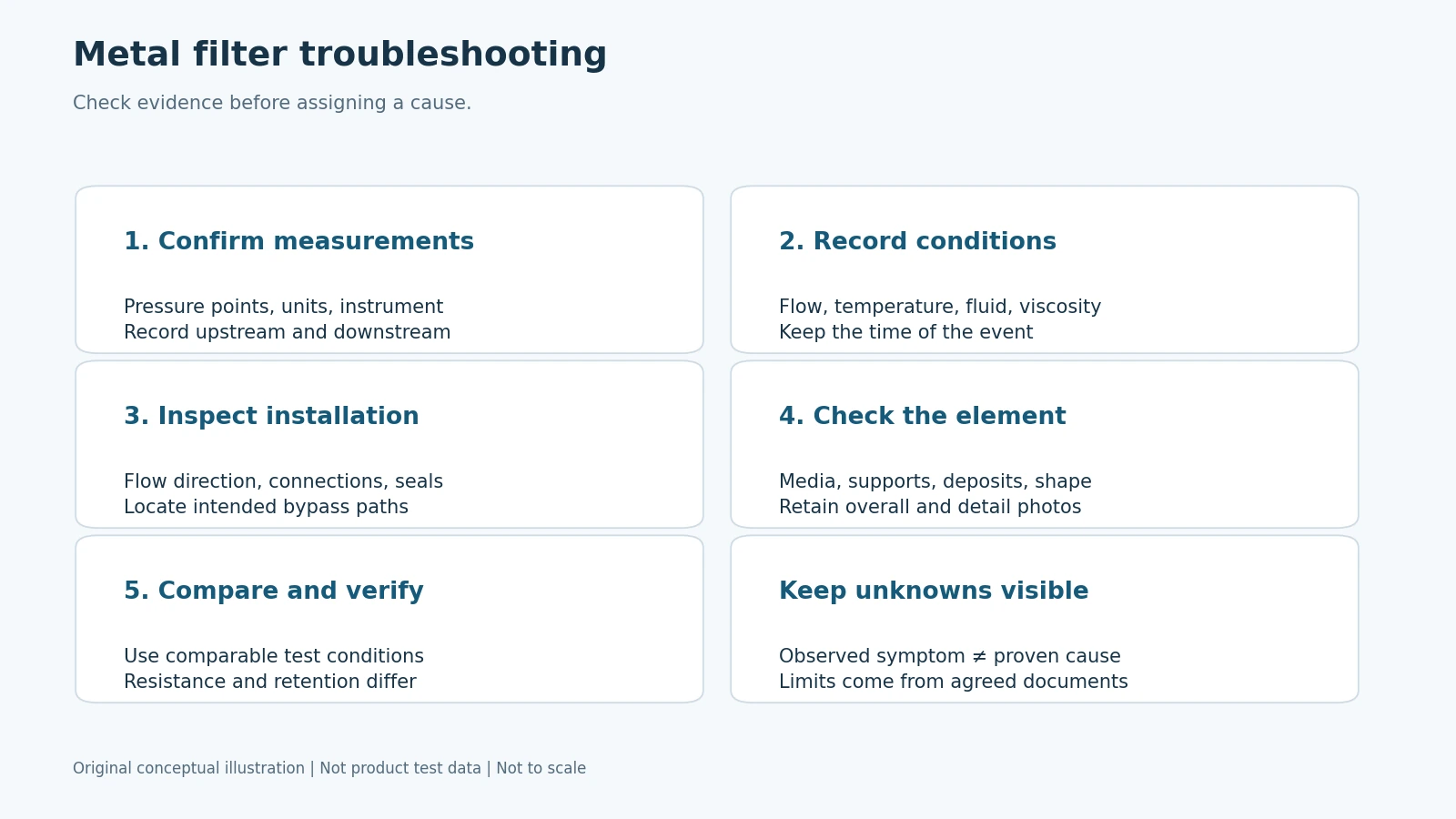
Original conceptual diagram: check evidence before assigning a cause. It is not a product test result.
Identify the pressure measurement boundary first. Are the taps immediately across the element, across the housing and connections, or across a longer pipe section? These boundaries produce different results. Use the same tap positions, units and instrument condition, and retain both upstream and downstream readings. A single pressure reading is not the element's differential pressure.
Record flow, temperature, fluid composition and available viscosity information. A clean element can have different pressure drops at different viscosities or flow rates. Parker's maintenance literature treats viscosity and element condition as separate considerations [1]; its model-specific alarm and replacement limits are not universal limits for metal filters.
A useful baseline comes from an identified new element or a validated clean condition. Record installation, flow direction and sampling conditions. If only an old sample is available, document its present condition without treating it as the original design specification. Flag changes in fluid, pump speed, valve position, pipework or media that make comparison with the old baseline uncertain.
Describe the event precisely: “pressure drop rises over successive runs at the same flow and temperature,” “high during cold start, lower after warming,” or “high immediately after cleaning.” A pattern is a clue, not proof of a particular cause.
2. Compare symptoms and checks
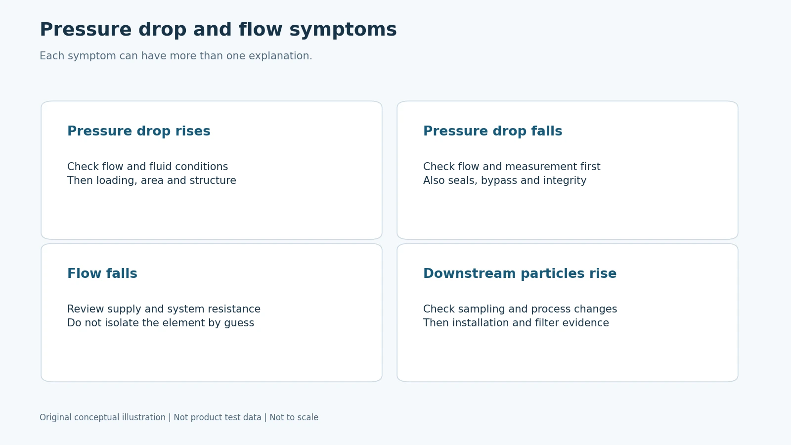
Original conceptual diagram: each symptom can have more than one explanation.
| Observed symptom | Directions to investigate | Evidence to obtain first |
|---|---|---|
| Pressure drop rises gradually | Particle loading, deposition, fluid changes, reduced usable area | Trends under comparable conditions and contamination records |
| High pressure drop at startup | Viscosity, temperature, flow, measurement boundary, element grade or area | Cold/warm comparison and clean baseline |
| Pressure drop falls suddenly | Lower flow, measurement error, bypass, seal or element changes | Flow, both pressure readings, particles and installation records |
| Flow decreases | Supply conditions, valve position, system resistance, fluid changes | Pump/system information and measurement boundary |
| Downstream particles increase | Sampling differences, bypass, seals, damage, unsuitable grade | Comparable samples and element/seal inspection |
| Resistance remains high after cleaning | Residual deposits, structural change, different test conditions | Cleaning record and repeat measurements under the same conditions |
| Element dents, bulges or shows end damage | Differential-pressure direction, transients, support, installation, material condition | Full photographs, flow direction and event log |
Use this table to organize investigation. It does not diagnose the element automatically or define acceptance. Several explanations can coexist: falling flow affects differential pressure, while a seal bypass can independently affect downstream particles.
Media-specific follow-up checks
The general symptom matrix applies first. The following observations help locate the next inspection on a particular structure; they do not assign a failure cause from appearance.
| Object and observation | Distinguish between | Next evidence and related guide |
|---|---|---|
| Powder body: poor recovery after cleaning | Separate accessible surface deposits from possible retained contamination within the porous wall. Compare the active porous region, dense end zones and connections. A dirty exterior does not locate every restriction. | Retain the cleaning record and repeat flow/resistance measurements with aligned fluid, temperature, area and pressure boundary. Inspect accessible surfaces and keep required integrity or retention checks separate. See powder-metal filter forms. |
| Powder body: metal-like particles, cracks or a local flow change | Consider the upstream system, housing, connections and seals as well as the porous body. Particle appearance alone cannot establish powder shedding, corrosion or a manufacturing defect. | Map the observation and keep upstream/downstream samples, particle-source evidence and body/end-joint photographs. For an asymmetric powder element, retain the specified fine-layer position and flow direction. |
| Woven mesh: changed flow or particles after cleaning | Distinguish blocked openings from moved or broken wires, distorted edges, seams and housing seals. Higher flow can coexist with enlarged openings or bypass. | Compare intact and affected areas using mesh measurement records; map loose wires, local openings and edges with the mesh inspection guide. Inspect joints and their filtering role separately from the cloth. |
| Etched sheet: restricted flow or local hole damage | Separate an initial restriction from later deposition. Examine identified hole regions, solid borders and any formed seam, support contact or seal; a pressure or particle change alone does not identify an etching defect. | Retain both-face and edge views, sample state and the drawing’s hole definition. Compare local damage with an intact region and known flow conditions. Keep the etched filtering sheet geometry separate from the assembly’s retention requirement. |
| Leaves and stacked discs: local leakage or damage | For a pressure leaf, locate the frame edge and outlet connection. For a polymer leaf disc, identify the center ring and outer edge. For a stack, identify the affected layer, spacing and support. | Retain an assembly/position map before dismantling and compare corresponding surfaces and seals. Use the relevant pressure filter leaf, polymer leaf disc or SPL/DPL element drawing; preserve unknown original dimensions. |
For knitted elements, separate the task before transferring acceptance criteria: demister diagnosis addresses droplet capture, loading, drainage and bypass; the knitted filter guide addresses the specified filtration element. Mechanical supports need load and displacement evidence; use the metal cushion guide and converter support guide for those roles. A droplet-carryover observation is not a solid-particle efficiency result.
3. Check rising pressure drop
Confirm the readings and fluid
Check for mixed units, changed taps and instrument issues. Review zero, range and calibration information where available. Retain unusual readings instead of smoothing them away.
Then check flow, temperature and viscosity at the time of measurement. Temperature changes can substantially affect flow resistance. Changes in solids, crystallization, colloids or reaction deposits require process-specific investigation. A single room-temperature viscosity value does not describe every operating condition of a non-Newtonian fluid.
Check loading, area and structure
Accumulated contaminants may restrict flow paths. However, a finer grade, smaller effective area or different support structure can also increase resistance. Matching outside diameter and length does not establish equal filtration area or the same flow–pressure-drop behavior.
For pleated elements, define whether folded, sealed, overlapping and obstructed portions are included in the area. Distinguish the media's resistance from that of the outer cage, inner tube, end caps and housing. Record where the observation was made rather than assigning the entire assembly's pressure drop to one mesh layer.
Make comparisons within the equipment's permitted operating conditions. Maintenance decisions need confirmed operating limits, downstream requirements and integrity criteria. Increasing operating pressure, removing the filtering layer or opening a bypass is not a general diagnostic procedure.
4. Investigate falling pressure drop and particle breakthrough
A sudden decrease first calls for checks of flow, taps and instruments. If downstream particles also increase, investigate bypass paths, seals, end connections, media and installation direction. Lower resistance alone is not evidence of successful cleaning.
NIOSH guidance treats air-filter bypass and installation as separate issues [2]. This is a useful distinction; the sealing arrangements and tests for a liquid element still need to match its application.
Keep sampling position, sample volume, counting method and particle-size definition comparable. An increase in one sample may reflect a process change, a contaminated sample container or another system component. Follow the evidence before attributing it to damaged media.
When using beta ratio or count efficiency, retain upstream and downstream data on the same basis. An apparently intact element does not prove that welds, end caps and seals have all been verified. Visible damage likewise does not establish remaining pressure capability from a photograph. See the filter micron rating and efficiency guide for the distinction between geometry and removal performance.
5. Check low flow and deformation
For low flow, review supply, valves, pipework, fluid and the resistance of the filtration section together. Pump discharge pressure and the pressure difference across an element describe different conditions.
Record whether deformation is inward, outward, local or concentrated at an end. Note whether it appeared during operation, startup, cleaning or handling. Compare actual flow direction with the internal and external support. Pulsation, reverse flow, mechanical loading and material condition are investigation directions, not conclusions established by one dent.
Preserve overall views, both ends, connections, support and close views of the affected area. Identify the sample's condition. Initial investigation need not destroy the sample. If sectioning, dismantling or material analysis is required, retain the original evidence and agree on the investigation first.
6. Evaluate recovery after cleaning
Pressure drop recovery is meaningful when conditions are consistent or their differences are documented. Different flow rates, temperatures or tap positions prevent attributing the entire change to cleaning.
Record cleaning method, fluid, time, temperature, direction and number of cycles, and identify parameters taken from the approved procedure. Metals, joints, seals and contaminants can require different conditions. Cleaning does not guarantee restoration of every sintered or pleated element to new condition.
Check resistance, visible condition and the required integrity or filtration performance separately. Restored resistance with inadequate retention still fails the application requirement. Incomplete resistance recovery calls for checks of remaining deposits and test differences.
Use the cleaning pressure-drop recovery calculator for comparable measurements and the measured flow–pressure-drop tool to organize multiple points. These tools process input data; they do not diagnose seals, damage or material suitability.
Felt-element checks after replacement or cleaning
| Observed pattern | Separate investigations | Related explanation |
|---|---|---|
| High resistance immediately after replacement | Flow and fluid comparison; grade and effective area; support and passages | pleat depth, density and usable area |
| A pressure-drop fall with increasing downstream particles | Sampling; seals and bypass; end joints and media condition | shedding and delivery cleanliness |
| Repeated high resistance after cleaning | Comparable test conditions; residual deposits; construction changes | fiber felt cleaning and reuse |
These observations guide the next check; they do not identify a cause by themselves. Keep the assembled condition, seal positions and both end connections in the record before dismantling. A particle shaped like a fiber needs source evidence, while lower resistance needs a separate check of the filtering boundary.
For a comparable loading result, see dirt holding capacity and service life. Capacity and service life should not be inferred simply from a felt’s porosity or from how long a previous element ran.
Sintered mesh layer, edge and joint checks
For a multilayer sintered mesh element, distinguish the laminate from its cut edges, longitudinal seam, end connections and housing seals. Visible layer lines alone do not establish delamination. Record abnormal gaps, lifted edges or distorted areas at identified locations before assigning a cause.
| Observation | Checks that help locate the issue | What remains to be established |
|---|---|---|
| A lifted edge or apparent interlayer gap | Compare with the specified layup and an undamaged area; note whether it is at a cut edge, a bend or away from fabrication features. | Whether the feature is an actual bond defect, local processing damage or the normal layered edge appearance. |
| Falling pressure drop with increasing downstream particles | Confirm flow and sampling, then inspect seals, end joints, seams and exposed media separately. | The bypass or damage path. Neither delamination nor a manufacturing cause follows from this symptom alone. |
| Poor flow recovery after cleaning | Compare fluid, temperature, flow and pressure-tap boundary with the baseline; examine remaining deposits and accessible passages. | Whether retained contamination, changed test conditions or structural damage explains the result. |
| Deformation noticed after reverse cleaning | Record pressure direction, inner and outer supports, unsupported spans and where deformation starts. | Actual cleaning loads and component limits. A photograph alone cannot establish an overload or remaining pressure capability. |
Backwashing, ultrasonic and solvent cleaning need conditions compatible with the laminate, joints, seals and contamination. Follow the agreed procedure rather than applying a universal concentration, temperature or reverse pressure. After cleaning, compare resistance under aligned conditions and separately check the required integrity or retention. Restored flow does not by itself demonstrate continued filtration.
For the layer arrangement, see sintered mesh layers, support and flow direction. The sintered wire mesh manufacturing process distinguishes sheet inspection from checks after forming and joining.
7. Prepare a troubleshooting record
For every item, enter a value, unit, source or “unknown”:
- Equipment and complete element identification, quantity and installation position.
- When the symptom began and the latest replacement or cleaning.
- Tap diagram, upstream/downstream pressures, differential pressure and units.
- Flow, temperature, fluid, viscosity and contaminant changes.
- New-element or validated clean baseline.
- Element dimensions, media, grade definition, direction and support.
- Available seal, bypass and other functional-component information.
- Downstream target, sampling position, method and results.
- Overall/local photographs and deposit or deformation observations.
- Actions taken, repeat-test conditions and unresolved questions.
For a new project, discuss structure and operating requirements. For drawing-based manufacture, retain the drawing revision and acceptance conditions. For sample-based work, establish measurable geometry and dimensions; unknown original performance or material information cannot be filled in from appearance. The replacement cartridge measurement guide helps organize dimensional records.
8. Frequently asked questions
Does high differential pressure always mean a clogged filter?
No. Check flow, fluid, temperature and measurement boundaries before loading and structure.
Does lower pressure drop prove that cleaning worked?
Confirm comparable flow, seals, element integrity and the required filtration performance.
Can one pressure gauge establish element differential pressure?
One pressure reading does not establish the difference across an element. The measurement boundary must be clear.
Should a high winter startup reading trigger a change of grade?
Record temperature, viscosity and startup conditions first. One reading alone is insufficient.
Why can elements with the same dimensions have different pressure drops?
Media, effective area, support, connections and grade definitions can differ.
Does a large opening in the outer cage mean a coarser filter grade?
The cage may provide protection or support. Identify the actual filtering layer separately.
Can every original performance claim be retained after cleaning?
Resistance, integrity and filtration requirements need application-specific confirmation.
Can investigation begin without a historical baseline?
Yes. Keep current conditions and original readings, mark the baseline as unknown and identify the evidence needed next.
Summary
Confirm measurement first, review operating conditions next, then check installation, seals and structure and repeat measurements under comparable conditions. Separate symptoms, possible explanations and verified findings in the record.
References
- Parker CF/RF filter service and maintenance instructions. Hydraulic maintenance context; model-specific limits are not applied here.
- NIOSH 2003-136: filtration and air-cleaning systems. Background on bypass and installation; no historical air-rating table is reproduced.
The symptom matrix and record sequence are editorial guidance, not a complete procedure prescribed by a particular standard.
Author background: Jack Sun has long worked in metal wire mesh weaving and industrial filter element manufacturing. Our company is based in Anping, Hengshui, Hebei, China.