A data sheet can show a micron rating, a porosity percentage and an air-permeability figure in the same row. Those numbers do not form a conversion table. Before deciding that two materials are equivalent, establish what each result measured and whether the evidence applies to the form you intend to purchase.
This guide explains how to review the data. Available materials and supply forms remain on our sintered metal fiber felt product page.
1. Identify the material and test object
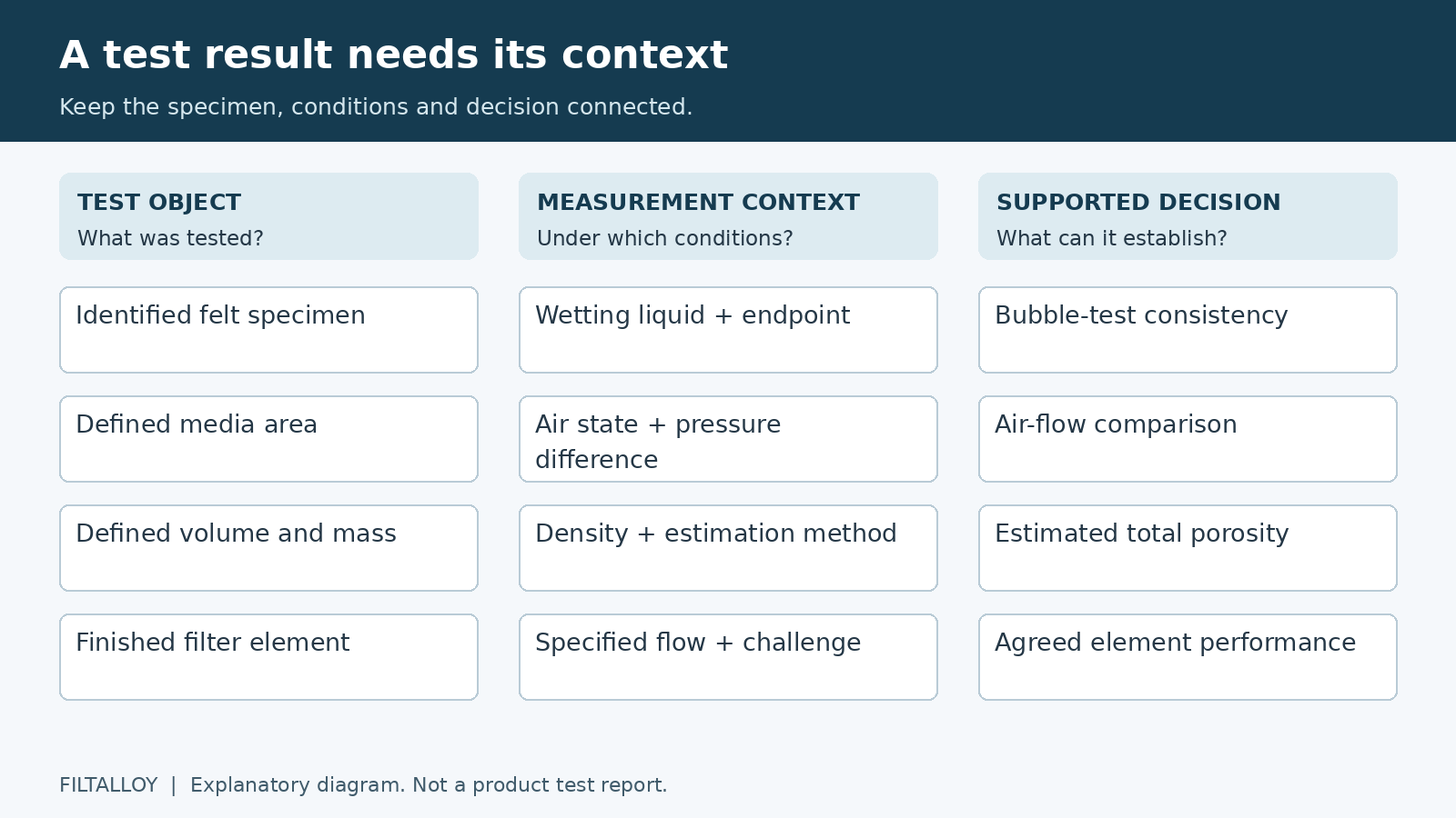
Start with the alloy, product code, construction revision and supply condition. Establish whether the figures describe unsupported felt, felt bonded to supporting mesh, a cut specimen or a complete cylindrical or pleated element. A media specimen and a finished filter are different test objects.
Ask whether a support layer is included in the stated thickness, mass and test area. A table without a material assignment should not be interpreted as applying every row to 316L, titanium or nickel. The material and construction must be traceable to the data being used.
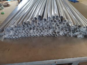
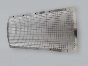
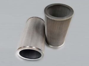
Photographs help identify forms, visible edges and supporting parts. They cannot establish alloy composition, a micron rating or batch conformity. Keep the specimen identification connected to the drawing, specification and inspection record.
2. Separate typical values from acceptance limits
A typical value describes representative behavior. An available range describes a supply envelope. An acceptance limit defines a decision about a delivery under agreed conditions. A catalog entry does not automatically become a guarantee for every sheet or every point on a sheet.
Check whether a result is an average, a minimum, a maximum or a single observation. Then establish sampling locations, sample count, measurement direction and reporting precision. An average thickness alone cannot demonstrate compliance with a maximum-thickness requirement. Sampled inspection should not be described as inspection of every piece.
Where both millimeters and inches appear, agree which is the governing unit. Rounded conversion values should not create a second, conflicting tolerance. The inspection plan should also state how measurement uncertainty is handled when making an acceptance decision.
3. Read thickness and porosity correctly
For thickness, confirm the specimen state, measurement locations and contact conditions used by the applicable method. Flexible, supported or multilayer media can produce results that should not be compared without this context. Do not invent a contact pressure when the report has not supplied it.
As a notation example, a nominal thickness of 0.50 mm with an explicitly relative tolerance of ±10% gives an arithmetic interval of 0.45–0.55 mm. This is an illustration of tolerance wording, not a Filtalloy test result or an acceptance rule for a particular grade.
Porosity describes the void fraction of a volume. It is different from the projected open-area percentage of square woven mesh, and it is not a filtration rating. Equal total porosity does not establish equal pore connectivity, flow resistance or particle retention.
A mass-and-volume estimate also needs the appropriate solid-material density and a defined specimen volume. Supporting layers, coatings, retained liquid and thickness errors can affect the estimate. Our sintered metal porosity calculator helps review these inputs and their arithmetic relationship; it does not measure pore distribution or filtration efficiency.
4. Understand the scope of bubble-point data
Bubble-point data concern gas passage through a wetted porous specimen under a defined procedure. Record the wetting liquid, temperature, specimen condition, exposed region, sealing and endpoint definition. Two pressures obtained with different conditions are not automatically a valid material comparison.
The public abstract of ISO 4003:1977 treats its bubble test as a quality-control method, rather than a way to define filter grades or an exact pore-size distribution. A report citing this method should not therefore be relabeled as proof of an absolute particle-retention rating.
Within a defined product and consistent procedure, an agreed bubble-point range can contribute to consistency checks. An unexpected result should prompt investigation of wetting, sealing, specimen state and other relevant evidence. A single pressure result does not, by itself, identify a particular manufacturing defect.
5. Compare air-flow results with their conditions
A column called air permeability may report an air volume per unit area per unit time at a particular pressure difference. Ask for that pressure difference, the air temperature and pressure, the flow-reference basis, the exposed area, flow direction and specimen construction. Without them, the displayed numbers may be unsuitable for ranking suppliers or predicting service behavior.
Unit-conversion example: 60 L/(dm²·min) equals 0.10 m/s because 0.060 m³ divided by 0.01 m² and 60 seconds is 0.10 m/s. This only converts volume flow per area to a velocity. It does not determine intrinsic permeability or the pressure loss of a liquid filter. The figure is illustrative, not product test data.
ISO 4022:2018 addresses fluid-permeability testing of interconnected sintered-metal structures through viscous and inertia permeability coefficients. A flow result at one pressure difference and a defined model coefficient are different outputs. Check the actual quantity and its units.
Also establish the specimen’s cleanliness. Initial clean-media data do not predict contaminant capacity or replacement intervals. Deposits, fluid properties and cleaning history can change the comparison. Use the filter area calculator only for the relevant geometric area step, with the finished configuration clearly defined.
6. Keep filtration rating and efficiency separate
A micron is a unit of length. A “10 μm” filter designation still needs a rating definition. Nominal, absolute and proprietary grade descriptions should not be treated as equivalent without the test and acceptance basis that gives them meaning.
For a particle-retention comparison, identify the challenge material and particle-size expression, fluid, flow, counting method, endpoint and test object. A media test does not automatically establish complete-element performance. A pore-related result should not be substituted for a particle-efficiency measurement.
Our filter micron rating and efficiency guide explains rating terminology and beta ratios in more detail. Here the purchasing task is to retain the definitions needed to interpret the actual report.
A useful next step when two “10 μm” sheets differ
If one sheet lists an air-flow value and another lists only bubble point, neither result fills the missing particle-retention definition. Start with the property the project must verify. Ask for the grade definition for retention, aligned flow conditions for resistance, or the agreed final-state method for batch consistency.
Record an unavailable result as missing rather than zero. Do not interpolate a nominal grade between table rows or apply a coupon value to a complete cartridge without checking construction. The mechanisms are covered separately in felt permeability and pressure drop and dirt holding capacity and service life; this page keeps the report fields and their acceptance meaning together.
7. Move from media to the finished element
Finished construction introduces active area, pleat spacing, support masking, seams, end connections, seals and flow direction. These features may change pressure loss or create paths that a flat-media specimen does not represent.
A media tensile-strength value cannot be converted into an allowable differential-pressure rating for a finished filter. Test direction, specimen geometry and cross-sectional-area definitions need their own interpretation; component loading and structural validation are separate questions.
Specify the media and the finished element together. Use media data to screen construction options, and the drawing, dimensional checks and applicable performance verification to assess the actual delivery. If reviewing used filters, the metal filter troubleshooting guide provides a separate framework for documenting operating changes.
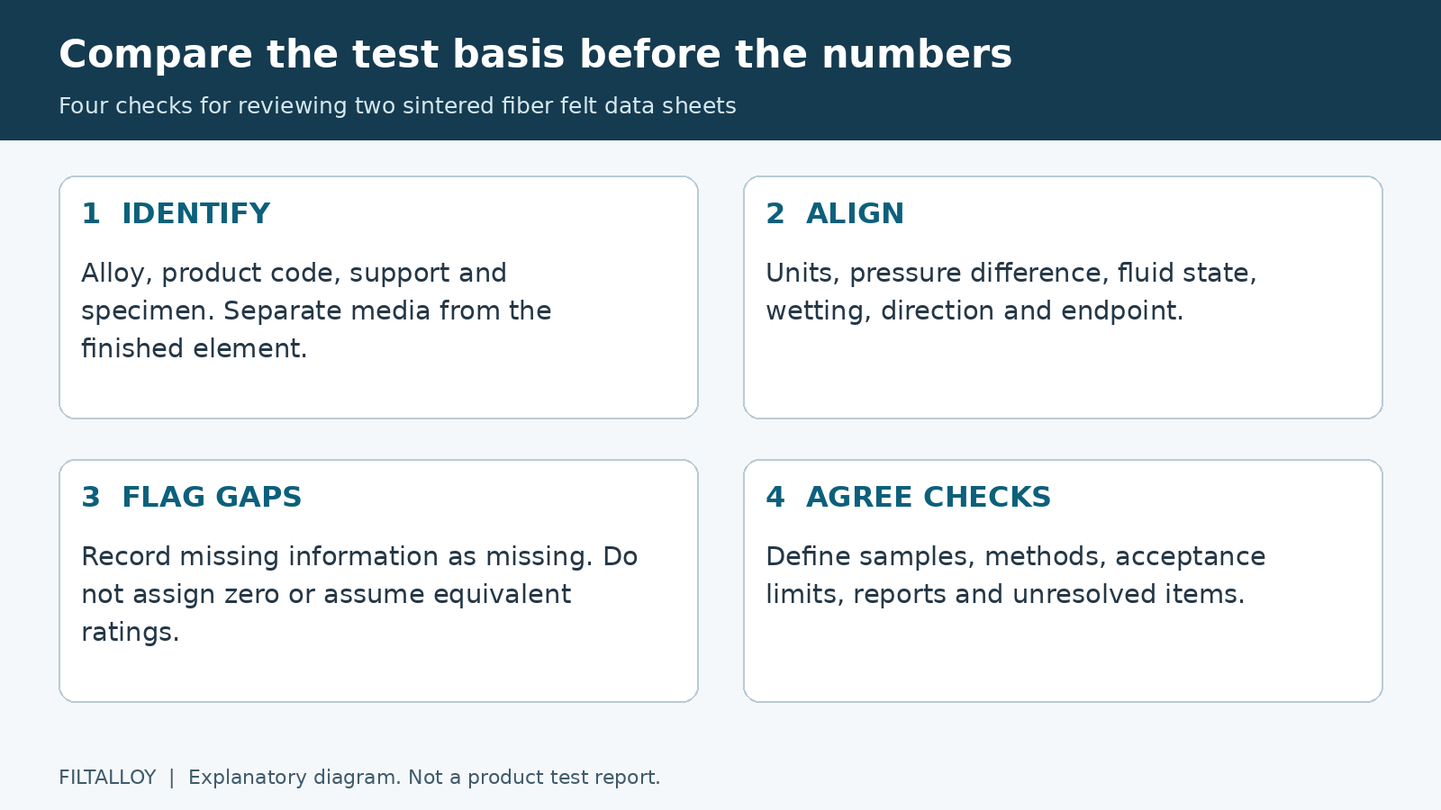
8. Review two data sheets systematically
| Reported item | Context to align | Decision to avoid |
|---|---|---|
| Material and structure | Alloy, product code, support and batch identity | Assigning an unstated alloy to all rows |
| Thickness | State, method, locations, tolerance and main unit | Accepting a maximum requirement from an average alone |
| Porosity | Volume definition, method and density inputs | Equating void fraction with pore size or efficiency |
| Bubble point | Wetting, temperature, sealing and endpoint | Calling it an absolute particle rating |
| Air-flow result | Pressure difference, air state, area, direction and units | Comparing values with unknown test conditions |
| Filtration rating | Rating definition, challenge, procedure and test object | Declaring equivalence from the same micron label |
| Delivery conformity | Sampling, limits, records and deviation disposition | Treating a typical value as a delivery guarantee |
For example, two sheets may both say “10 μm,” while one includes an air-flow number and the other only a bubble-point result. The next step is not to declare one superior. Identify whether the project needs evidence about initial resistance, particle retention or batch consistency, then request the corresponding information. Mark unavailable information as missing, not zero.
9. Turn the review into purchasing requirements
For manufacture to an existing drawing, start with that drawing or specification and the required quantity. Keep its media, finished dimensions and acceptance references together. Clarify missing definitions or construction details as needed; service conditions become part of the discussion when suitability or a design change must be assessed. The resulting records can link the media specification, finished-element drawing and agreed delivery checks.
For each important property, identify the test object, method and decision rule. Useful clarification items include the product code, thickness tolerance, porosity method, filtration-rating definition, bubble-test conditions, air-flow test pressure difference, assembly direction, sampling plan and required batch-related report.
Not every project needs every possible test. The selected checks should answer the agreed requirements. Where two data sets cannot be compared, seek a common test basis or an agreed representative-sample evaluation. Record revisions, dates and unresolved items before fixing delivery limits.
Frequently asked questions
Does higher porosity mean finer filtration?
No. Void volume alone does not determine pore geometry or particle retention. Review structure and the appropriate filtration evidence.
Is a higher bubble point always better?
First establish comparable conditions and the project requirement. Bubble point is not a universal performance score.
Does a standard number make two air-flow figures comparable?
The report must still identify the specimen, conditions, units and reported quantity. A method reference cannot supply missing pressure or air-state information.
Can porosity and thickness predict dirt holding capacity?
They do not provide a reliable service-capacity prediction on their own. Contaminant, fluid, flow, endpoint and finished area matter; comparable measurements are needed.
Does conforming media prove the finished filter conforms?
No. Cutting, forming, joining, connections and sealing introduce additional features that should be checked against the finished-product requirements.
Read the number together with its evidence
Start with material and test-object identity, then review conditions, units and the type of value reported. Finally decide which purchasing question the evidence can answer. A clearly recorded information gap is more useful than an assumed equivalence.
For available media and fabrication forms, review our sintered metal fiber felt range. To discuss a project, send operating conditions, a drawing or sample information, including the property and acceptance basis you need to verify.
Related fiber felt guides
- Sintered Felt Permeability and Pressure Drop
- Pleated Fiber Felt Design: Depth and Density
- Fiber Felt Dirt Holding Capacity and Life
- Sintered Fiber Felt Cleaning and Reuse
- Sintered Fiber Felt for Polymer Melt Filtration
- Sintered Fiber Felt: Mesh Support Selection
- How Layup and Sintering Shape Metal Fiber Felt
- Pleated Fiber Felt Filter Validation Plan
- Metal Fiber Felt Shedding and Cleanliness